Communication circuits
Communication systems of electric utilities have become increasingly critical to electric system protection, operation, and maintenance. For fast tripping and clearing of system faults, communication-aided relaying has become a common protection scheme, particularly in line protection.

Control centers depend on reliable communication channels to remotely operate substation circuit breakers and switches, telemeter electrical quantities of the electric system, and monitor substation alarms.
Maintenance engineering has also become increasingly dependent on communications for remote access to intelligent electronic devices such as relays, remote terminal units, digital fault recorders, and revenue meters.
The area of communication can be split into three areas:
- Internal communications: the communication system design internal to the substation that feeds into the external communications and documents relay-to-relay communications;
- SCADA: details of the documentation unique to SCADA data; and
- External communications: inter-substation communications and the details of the communication media used.
Note that these three areas of communication are all integrated with each other, and there is overlap between these areas.
1. Internal Communications
IEEE Std C37.1 discusses the importance of block diagrams, addressing the communication block diagram in more detail. The communication block diagram provides a similar function for the communication system as the substation one line provides for the electrical design.
Before any communication design begins, all of the internal and external connections to IEDs should be put on a drawing.
These circuits include:
- Remote SCADA communications to one or more entities and/or utilities for operational data
- Remote communications to one or more entities and/or utilities for nonoperational data
- Inter-substation protective relay communications via various transport methodologies:
- Dedicated fiber using proprietary communications
- Serial multiplexed signals to a SONET ring
- Power line carrier (PLC)
- Ethernet
- Leased telco circuits
- Radio/microwave circuits
- Local telco circuits for substation phone and/or data circuits
- Revenue metering data circuits
Entities involved for each of these circuits can be one or more utilities, power plants, and independent system operator.
IED Connections
The communication block diagram should detail the following connections for each IED:
- Device designation
- Device part number (optional)
- RS-232 serial communication ports with connector type (terminal block, DB9 male/female) and port number with front or rear indicated as necessary
- RS-485 serial communication ports with connector type (terminal block, DB9 male/female) and port number or terminal block number with front or rear indicated as necessary
- Ethernet ports with connector type and speed (RJ45: 10/100BaseTX, 10/100/1000BaseTX; ST, MTRJ, LC: 10BaseFX, 100BaseFX) and port number with front or rear indicated
- IRIG-B port with connector type (coax, terminal block) and modulation, with a port number or terminal block number with front or rear, indicated as necessary
Device designations can use device number 16 when appropriate. C37.2 added device number 16 to refer to data communications devices and lists suffixes to identify the functions. The first suffix indicates whether the device is serial (S) or Ethernet (E). Subsequent suffixes indicate the following functions: security processing (C), firewall (F), network managed (M), router (R), switch (S), and telephonic (T).
Device designations on the block diagram should match those assigned on nameplates and drawings to provide consistency across the design documentation.
The communication block diagram should connect communications ports together, with cable types indicated by line type and/or line annotation. The organization of the communication block diagram is very important, as the diagram can quickly become a mess of lines that is difficult to read and understand.
Figures 1, 2, and 3 are examples of block diagrams. Figure 1 shows a small, simple block diagram for a metering system connected to a generation plant with IRIG-B
connections and network connections are shown.
Figure 1 – Example Block Diagram #1 (click to zoom)
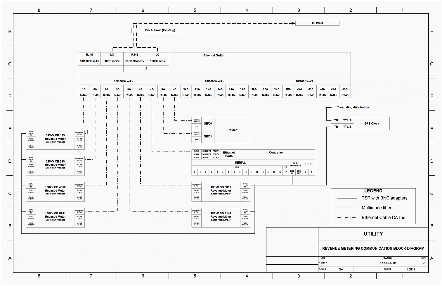

Figure 2 shows a detail from a larger, more complex conceptual block diagram for a complete substation automation system without the IRIG-B distribution shown. This drawing was completed at the conceptual design stage, well before any detailed design was started. Some protective relay communications are shown.
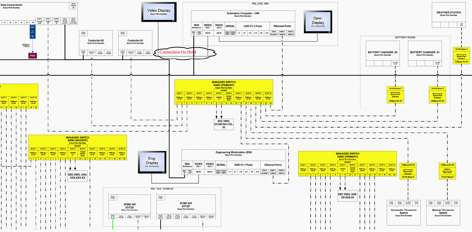
Note the use of device number 16. For example, 16ERFCM indicates an Ethernet router, managed, with a firewall and VPN for cyber-secure communications.
Figure 2 – Detail from Example Block Diagram #2 (click to zoom)


Figure 3 is a detail from an even larger, more complex block diagram for part of a substation automation system that shows IRIG-B distribution. At the point of the design process, Figure 3 had not yet captured the protective relay communication requirements.
Figure 3 – Detail from Example Block Diagram #3 (click to zoom)

Go back to the Contents Table ↑
2. SCADA Documentation
SCADA is an important part of substation control and protection and its integration to protective relay schematic is very common. The SCADA equipment discussed in this
section is referred to as Substation Remote Terminal Unit (RTU).
This section does not cover the SCADA – Energy Management System that is the SCADA master at utility control/operation center.
The following information is important to include in representing substation SCADA-related control/equipment in the schematics.
- Functional/Network diagram (firewall, router, switch, IED, meters, HMI, transducers, multiplexer)
- Protocols: DNP3, Modbus, etc. (learn more on this)
- Communication interface/pinout (ie. RS 232, null modem, RJ45, Fiber optic, etc.)
- Port Communication setup (baud rate, stop bit, parity, etc.)
- Cyber-security critical infrastructure perimeter diagram (learn more on this)
- Communication media (copper, fiber, microwave, etc.)
- Communication circuit ID and type (analogs, digitals, frame relay, T1, Sonet, etc.)
Where possible, SCADA-related controls are to be identified in the schematic by the unique box or text font for easy identification. The same issues as in microprocessor relays are encountered in SCADA equipment. For example, a Remote Terminal Unit sometimes has logic built in the programming. It is sometimes difficult to decide how much of that program inside the RTU should be documented on the schematic diagram.
Suggested Reading – The essentials of automation applied to distribution systems via PLCs, SCADA, IEDs, and RTUs
The essentials of automation applied to distribution systems via PLCs, SCADA, IEDs, and RTUs
Many utilities use separate table/spreadsheet-based documentation outside the schematic. Any pertinent information to protocol/s used in the SCADA system needs to be documented either in this document or the schematic.
The point list can be a valuable design control document as well as a testing document. The point list is usually in a spreadsheet format, with separate worksheets for:
- Cover sheet
- Connection sheet
- Status
- Control
- Analog inputs
- Analog outputs
- Accumulators
The cover sheet contains a revision block and site name. The connections worksheet can detail the communication settings for the ports being used in the system, with serial port and network port settings showing relevant information about the connection type. Serial connections can show baud rate, data bits, stop bits, parity, slave address, master address, and protocol. Network connections can show port speed, IP address, subnet mask, default gateway, master address, slave address, and protocol.
Each worksheet for data points has a different format, with appropriate columns depending upon the system functionality:
- Point number
- Point name
- Point description
- Alarm state
- On description
- Off description
- Comments
- Scaling (min, max, offset, counts)
- Units
Even with IEC 61850 substation automation systems, the point list can be a valuable tool to define what points are actually required from each IED and where that data goes. So the function turns into a design control document that IED configuration files can be created to match.
If in a diagram, it is important for the data flow to show at least the initiating connection and identify the protocol being used along with the associated TCP port number.
Suggested Reading – Why functional specification is essential for the success of a SCADA project
Why functional specification is essential for success of a SCADA project
Go back to the Contents Table ↑
3. External Communications
Electric utility communication systems are typically unique and proprietary to the electric utilities that own them. Hence, approaches to the documentation of these systems may vary from utility to utility.
However, there are documentation approaches that are common among electric utilities such as communication system maps, drawings and diagrams, and databases of utility-owned communication assets, channels, and leased lines.
Go back to the Contents Table ↑
3.1 Communication System Map
A communication system map is useful in depicting a bird’s eye view of the electric utility’s backbone communication system which is typically composed of microwave radios and fiber optic cables. The actual locations of major communication sites or terminals are typically indicated on the service area map of an electric utility as dots.
Other useful data that can be included on the map are the azimuths and elevation of microwave antennas, heights of microwave towers, lengths and types of fiber optic cables, and other pertinent information peculiar to each terminal or site.
Go back to the Contents Table ↑
3.2 Communication System Layout Diagram
The purpose of a communication system layout diagram is to document all communication devices used at a communication site or terminal and to depict how these devices are interconnected with each other. The devices include microwave radios, fiber-optic multiplexers, digital access cross-connect switches (DACS), routers, channel bank assemblies (CBA), and T1 protection switches.
An example of a communication system layout diagram is shown in Figure 4.
Figure 4 – Communication System Layout Diagram (click to zoom)


In this example, the communication terminal, located in a substation, directly supports a control center. As shown, the backbone communication devices such as microwave radios and fiber optic SONET OC-3 multiplexer are documented and drawn to show how they are interconnected with other devices.
As observed, the communication system layout diagram is a high-level representation of a communication system at a substation or communication terminal. Typically, interconnections between devices are shown at DS1 and higher levels of digital communication only.
Go back to the Contents Table ↑
3.3 Microwave Radio and Fiber Optic Communication Systems Diagram
Figure 5 is an example of a microwave radio communication system diagram that documents and presents the components of microwave radios in a substation or communication terminal. Detailed information relating to the antennas and waveguides is documented in this diagram. Specific parts of the antenna-waveguide system are documented for ease in maintenance.
Block diagrams showing the types of radio transmitter-receiver, multiplexers, and channel bank assemblies and their interconnections are presented. Also shown in detail is the 48Vdc power supply system that supports the radios.
Figure 5 – Microwave Radio Communication System Diagram (click to zoom)


The fiber optic communication system diagram documents terminal devices associated with fiber optic communications in substations. An example of this diagram is shown in Figure 6.
Figure 6 – Fiber Optic Communication System Diagram (click to zoom)
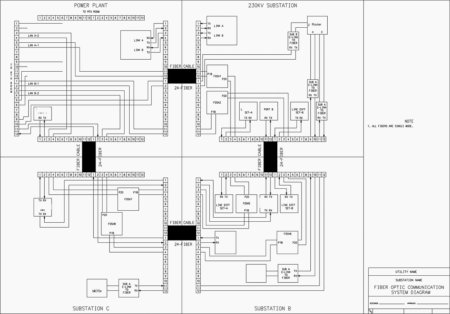

As shown, fiber patch panels and their terminals are clearly indicated in the diagram. Communication devices and relays that use direct fiber communications are drawn showing their fiber optic ports and their fiber connections to and from the patch panels. Patch panel terminals are clearly indicated in the diagram.
This information is very critical in troubleshooting optical fibers.
Go back to the Contents Table ↑
3.4 Communication Channel Circuit Diagram
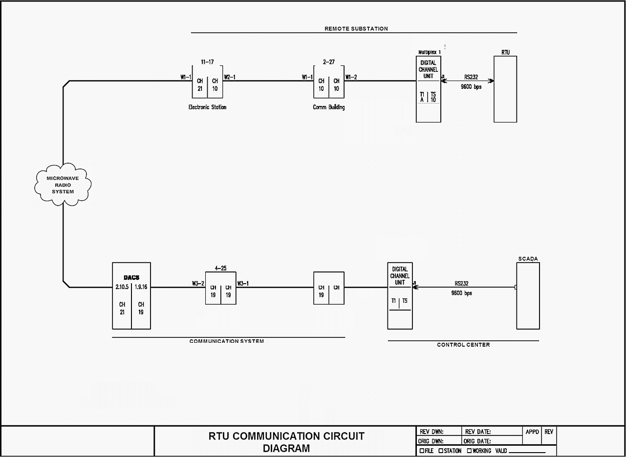
One method of documenting communication channels is by drawing out the entire communication circuit between the communicating devices as shown in Figure 7. In this diagram, the devices that are communicating with each other are the RTU in a substation and the control center SCADA.
As communication channel is routed through channel banks and digital access cross-connect switches, channel assignments and communication circuits are documented. Baud rates, connector types, and communication protocols may also be documented on the diagram. Actual microwave hops and radio sites can be specifically indicated in the clouded microwave radio system.
Figure 7 – Communication Channel Circuit Diagram (click to zoom)

Go back to the Contents Table ↑
3.5 Database Documentation
For better accounting and management of electric utility assets, business applications such as asset management programs are commonly used in the industry. Communication system assets are entered and stored in the databases of these programs. The specific information of these devices including historical maintenance data is archived and managed in the database.
This database is linked to a financial database for tracking expenses of their maintenance.
An example of a report of a query from a database is shown in Figure 8.
Figure 8 – Database Documentation of digital access cross-connect switches (DACS) Channels
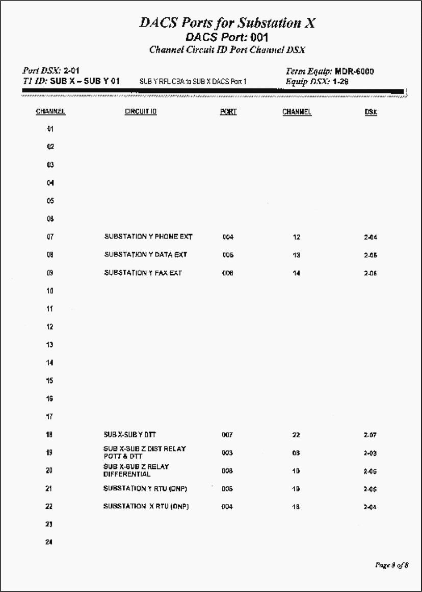

In this example, the cross-connecting channels to DACS Port 008 channels and circuit descriptions are documented. This database provides a convenient method for documenting, tracking, and managing channels through a DACS system.
Go back to the Contents Table ↑
Source: Schematic Representation of Power System Relaying by IEEE Working Group I5


Dear Sir,
Kindly could you do designs on request for a 66/11kv GIS Switchgear Substation with 2×7.5MVA and one ground mounted outdoor substation transformer of 200kva 11kv/400v.
Regards,
Jean Kinyua (Ms.)
Masterpiece Electricals Ltd
P.O. Box 72942-00200
Nairobi, Kenya
http://www.masterpiece.co.ke
Sir please give me FDF file on my email id For removing SCADA hanging problem .
Are your switchboards/switchgear digitalized ?