Busbar protection in general
A busbar protection is a protection to protect busbars at short-circuits and earth-faults. In the “childhood” of electricity no separate protection was used for the busbars. Nearby line protection were used as back-up for busbar protection. With increasing short-circuit power in the network separate busbar protections have to be installed to limit the damage at primary faults.

A delayed tripping for busbar faults can also lead to instability in nearby generators and total system collapse.
- Busbar protection – Requirements
- Principles of differential busbar configurations
- Switching in current circuits
- Protection of MV busbars in distribution networks
- Application of busbar protection
- Breaker failure relays
- Pole discordance (discrepancy) relays
1. Busbar protection – Requirements
Following requirements must be fulfilled. The busbar protection must have as short tripping time as possible. Also, busbar protection must be able to detect internal faults and must be absolutely stable at external faults.
External faults are much more common than internal faults. The magnitude of external faults can be equal to the stations maximum breaking capacity, while the function currents can go down to approximately 2% of the same. The stability factor therefore needs to be at least 50 times i. e. 20. CT-saturation at external faults must not lead to maloperation of the busbar protection.
1.1 Types of busbar protection
The busbar protections are mostly of differential type measuring the sum of current to all objects connected to the busbar, Kirchhoffs Law.
Differential type of busbar protections can be divided into three different groups:
- Low impedance.
- Medium impedance.
- High impedance.
For metal enclosed distribution busbars, arc detectors also can be used as busbar protection. For systems that are only radial fed blockable overcurrent relays in the incoming bays can be used as busbar protection.
2. Principles of differential busbar configurations
The simplest form of busbar protection is a 1-zone protection for single busbar configuration, see Figure 1. If the main CTs have equal ratio auxiliary CTs are not necessary. If the busbar protection is of the high impedance type the main CTs must have the same ratio and auxiliary CTs may then not be used.
Separate CT-core/s must also be supplied for the busbar protection. Other protection relays must be connected to other CT-cores.
For single busbar arrangement no switching is done in the CT-circuits and a check zone is therefore not necessary.


At 1 ½ breakers system arrangements a 2-zone protection must be used as in the Figure 2. If the main CTs have equal ratio, which is normally the case, auxiliary CTs are not necessary.


At double busbar switchgear a 2-zone protection shall be used, see Figure 3. If the main CTs have equal ratio auxiliary CTs are not necessary. CT-circuits are switched depending on the position of the busbar disconnectors. The current is either connected to busbar A or busbar B’s differential protection.
Switching is easiest performed by using repeat relays, controlled via two auxiliary contacts at each busbar disconnector, see Figure 5.
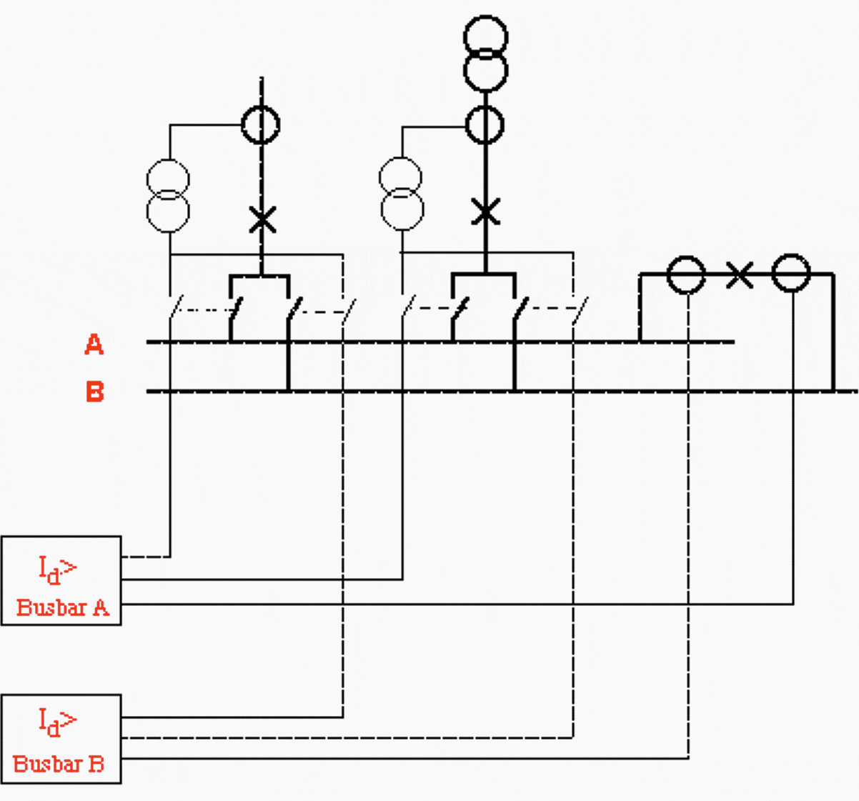

Many cases when switching in CT-circuit is done requires a check zone for the busbar protection, see Figure 4. The check zone is fixed and has no switching of CTs in all outgoing circuits and is not connected at busbar sections and busbar couplers.
The releasing when the check zone detects a fault is normally done by sending out positive DC-voltage to the discriminating zones.
Another way to do the releasing is to connect the negative DC voltage to all trip relays from the check zone and to connect the positive DC voltage from the discriminating zones.


3. Switching in current circuits
For busbar systems, where the object can be connected to more than one busbar, double busbar systems, the current must be switched to the correct zone busbar protection. This switching must be done in such a way that no differential current develops in any of the busbar protections concerned.
The switching is done by using two auxiliary contacts on the busbar disconnectors. These auxiliary contact are energizing throw-over relays which perform the switching in the CT-circuits. The disconnectors auxiliary contacts must be provided as in Figure 5.
Following requirements must be fulfilled by the auxiliary contacts “a” and “b” respectively:
- The auxiliary contact “a” must close minimum 100 ms before the main contact can start to carry current.
- The auxiliary contact “b” must open before the auxiliary contact “a” closes.
- The auxiliary contact “b”must not close before full insulation is secured (normally at 80% of the full insulation distance).


4. Protection of MV busbars in distribution networks
For busbars in distribution networks busbar protection can be achieved mainly in two different ways, either by blockable overcurrent protection at the incoming bays to the switchgear, or by locating arc detectors inside the enclosure.
Blockable overcurrent protection is based upon the principle that fault current is only fed by the incoming to the busbar.
For metal enclosed busbars, arc detectors can be used as busbar protection. The arc at a primary fault is detected by an arc sensitive device, which trips all incoming circuit breakers. In order not to risk maloperation due to photographic flashes etc., it’s advisable to also have an overcurrent interlock.


5. Application of busbar protection
As said above, for busbars in distribution networks the protection can be achieved mainly in two ways. The first one is by blockable overcurrent protection at the incoming bays to the switchgear, and the second way is by locating arc detectors inside the enclosure.
High impedance protection needs separate CT-cores with equal ratio at each feeder, bus-coupler and bus-section. This means that other protection relays cannot be connected to the same CT-core. This type of busbar protection is mainly for medium voltage levels.
Primary operating current varies with a factor 4 depending on in which phase the fault occurs. Phase indication cannot be obtained.
Recommended reading:
6. Breaker failure relays
In order to take care of possible breaker failure, Circuit Breaker Failure relays normally are installed in high voltage, and extra high voltage systems. All protection tripping (not manual opening) will start a current relay measuring the current through the CB. If the current has not disappeared within the set time, all adjacent CBs will be tripped to clear the fault.
The time “split up” at a normal tripping and a breaker failure tripping is shown in Figure 7.


In normal cases the total fault clearing time will be the protection relay operating time plus the CB interrupting time. Every time a relay gives a trip order it will at the same time start the Circuit Breaker Failure (CBF) relay. The CBF-timer will be running as long as the current is flowing through the CB. When the CB interrupts the current the CBF-current relay will reset and the CBF-timer will stop.
The setting of the CBF-timer must be: maximum interrupting time of the ordinary CB, plus the reset time of the CBF-current relay, plus the impulse margin time of the CBF-timer, plus a margin.
With “impulse margin time” is meant the difference between set time and the time “to no return”. If the timer is set to 100 ms and is fed during, lets say 98 ms, it will continue to operate since the margin between the set time and the actual time is small.
The margin should be chosen to at least 50-60 ms to minimize the risk of unnecessary tripping, specially considering the heavy impact on the network a CBF tripping will cause.
7. Pole discordance (discrepancy) relays
For circuit breakers with one operating device per pole, it is necessary to supervise that all three phases have the same position. This is normally done by using the auxiliary contacts on the circuit breaker according to Figure 8.
When single pole auto reclosing is used a blocking of the PD is necessary during the single phase dead time, see Figure 8.


The timing sequence at closing and opening of breakers and the timing of the operation at a pole discrepancy tripping must be checked carefully. It is e. g. often necessary to operate the flag relay first and the tripping from this relay to achieve correct indication at a trip as the main contacts will rather fast take away the actuating quantity when the remaining poles are opened.
Tripping from PD should be routed to other trip coil than the one used by manual opening. This is due to the fact that at manual opening, there could be an incipient fault in the circuit. This incipient fault could result in that only one or two phases operate and the MCB for the circuit is tripped. PD would thus not be able to operate if connected to the same coil as manual opening.
Operation of PD shall in addition to tripping the own circuit breaker start Circuit Breaker failure relay, lock-out the own circuit breaker and give an alarm.
A normal time delay for a PD relay should be approximately 150-200 ms when blocking during single pole Auto reclose is performed. If not the necessary time is about 1,2 sec.
Note: Some customers do not rely only on the auxiliary contacts and want to detect Pole discordance also by measuring the residual current through the breaker at breaker for some second at opening and closing.
Some manufacturers, like ABB have however good experience of the contact based principle and recommend only this simple principle.
Residual current measurement at closing and opening is not a reliable function either as there is no load current when a line is closed from one end only and on the other hand normal residual currents can occur if the closing is onto a fault or e. g. energizes a transformer at the far end of the system.
Conclusion is to use a simple contact based Pole Discordance function which is simple and reliable. The residual current based principle is more complicated and can give difficulties in setting of sensitivity etc.
Recommended reading:
Source: Transmission Systems and Substations by ABB
Copyright Notice
This technical article is protected by U.S. and international copyright laws. Reproduction and distribution of PDF version of this technical article to websites such as Linkedin, Scribd, Facebook and others without written permission of the sponsor is illegal and strictly prohibited.© EEP-Electrical Engineering Portal.
Related electrical guides & articles
Premium Membership
Edvard Csanyi
Hi, I'm an electrical engineer, programmer and founder of EEP - Electrical Engineering Portal. I worked twelve years at Schneider Electric in the position of technical support for low- and medium-voltage projects and the design of busbar trunking systems.I'm highly specialized in the design of LV/MV switchgear and low-voltage, high-power busbar trunking (<6300A) in substations, commercial buildings and industry facilities. I'm also a professional in AutoCAD programming.
Profile: Edvard Csanyi







Please assist with busbar protection pdf file. I also enjoy your articles they assist me to do more studies and reports in my line of work i.e power system analysis and network study
Please assist with PDF on overcurrent protection of 11kv distribution substation
Please send me pdf file of bus bar protection article
Sir, am the owner of electrical wind site, please suggest me how you grow your site ,
How can be a HV CB design Engineer?