
Estimated Study Time: 24 minutes
Mechanical and electrical interlocks
An industrial load with a connected load need above 2000 kVA usually requires multiple feeding transformers to restrict the system’s fault level. The fault level of an electrical network indicates the supply source’s capacity to withstand a faulty circuit, expressed in kVA or MVA.
 Interlocking of feeders to prevent parallel operation
Electrical network may also have a standby emergency supply source. The two feeding transformers, while electrically similar and capable of parallel operation, are not intended to operate in parallel to restrict the fault level.
To ensure mandatory safety by preventing parallel operation, it is imperative to implement a mechanical or electrical interlock, or both, between all incoming feeders.
This article discusses schemes that provide the necessary safety interlocks.
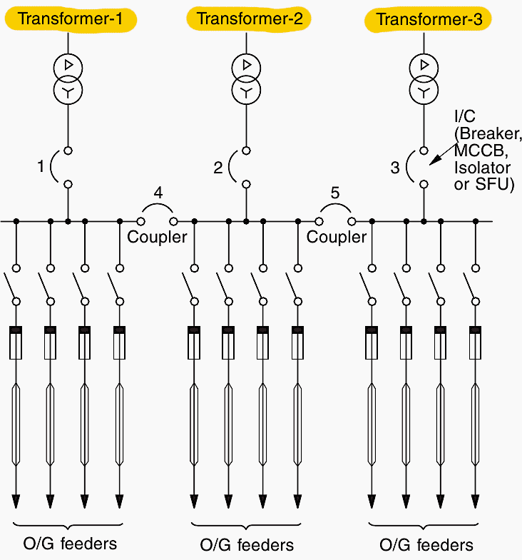
1. Schemes with more than one source of supply
When there are more than one sources of supply, it is advisable to distribute the loads also in as many sections as the incomers, and offer a tie-circuit between every two sections, to achieve additional flexibility. Now fault on one segment or source of supply will not result in power failure to the entire system.
Figures 1 and 2 depict this type of distribution. Current limiting fuses must be installed at both ends of potential/control transformers.
It is important to note that for big industrial and other LV loads, it is common practice to select multiple transformers with lower ratings to meet the needed load rather than a single transformer with greater capacity. Similarly, when more than one transformer is utilized to serve an important industrial load, the load must be distributed in as many sections as there are transformers.
Figures 1 and 2 depict a few typical but widely used distribution networks.
Figure 1 – Interlocking requirements for two-feeders system

Figure 2 – Interlocking requirements for a three-feeders system
2. Mechanical interlocking schemes
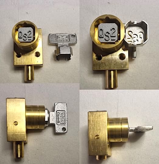
2.1 Use of switchgear castell locks
Different figure locks such as A – , – B and AB are used with a common master key. See Figure 3. The master key can unlock all locks A – , – B or AB because it has grooves for both A and B but will be locked with the lock that it unlocks.
For the removal of the key, the lock must first be locked. Only then can the key be used for the other locks, so accomplishing the required interlocking. The lock secures the lever of the interrupter’s closing mechanism, blocking its closure.
Lock AB can be unlocked by either of the keys A – or – B. The number of locks will be the same as the number of interrupting devices, but the keys will be less and will be for only as many interrupting devices as are permitted to be switched at a time (generally equal to the number of supply sources).
Figure 3 – Switchgear Castell locks
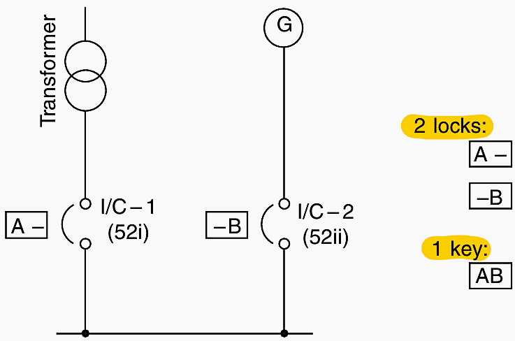
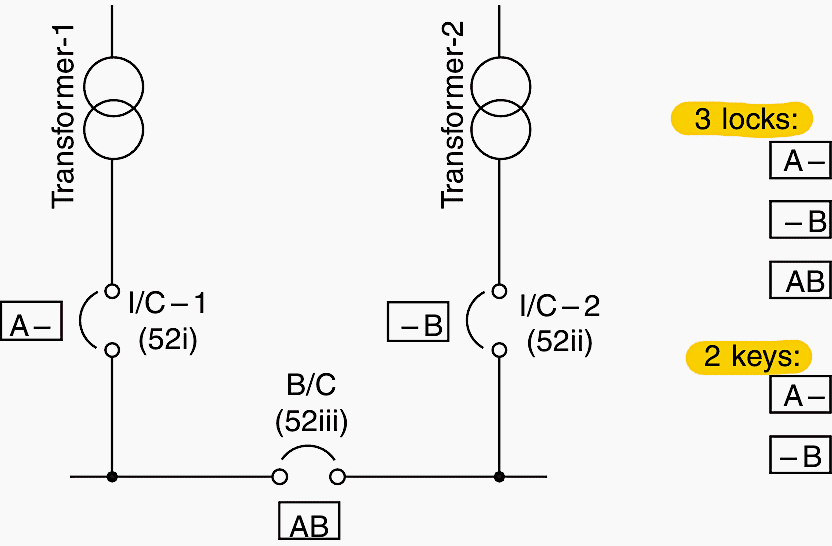
2.2 Scheme with two sources of supplie
The two incomers (I/C), fed from two different sources, can be fitted with two locks A – and – B , and one master key AB . This key will permit the switching of only one incomer at a time.
See Figure 4.
Figure 4 – Two sources of supply
2.3 Scheme with two sources of supplies and a bus coupler
The two incomers (I/C) and the coupler can be fitted with three locks, A –, – B and AB and two keys A – and – B : locks A – and – B for the incomers and AB for the coupler. The key A – can operate I/C-1 or the coupler and key – B can operate I/C-2 or the coupler.
Thus, only two of the three interrupting devices, I/C-1 and coupler, I/C-2 and coupler, or I/C-1 and I/C-2 can be switched at a time to achieve the required interlocking.
See Figure 5.
Figure 5 – Two sources of supply and a bus coupler
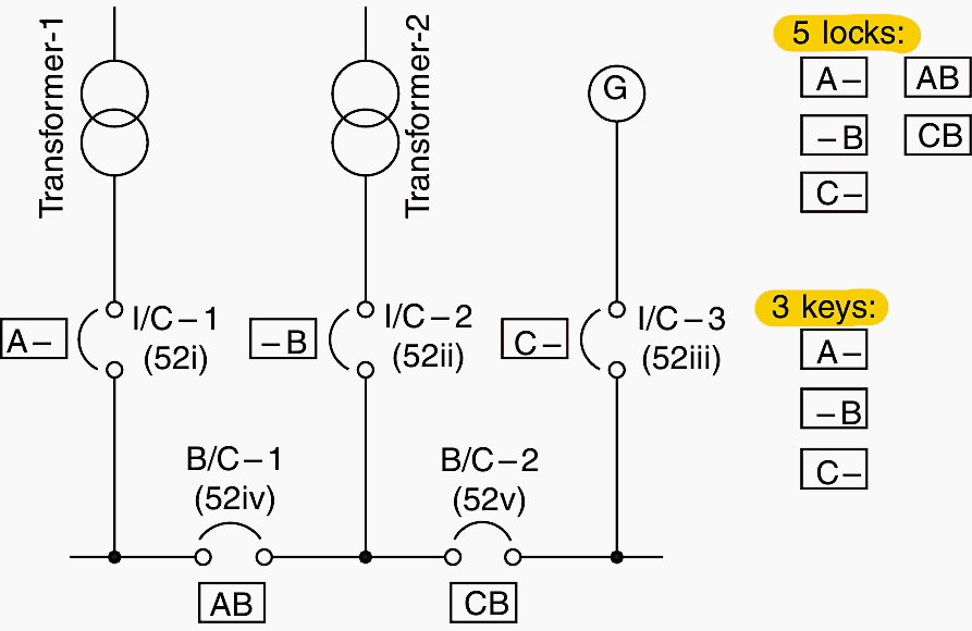
2.4 Scheme with three sources of supplies and two bus couplers
The three incomers and two couplers can be fitted with five locks, A – , – B , C – . AB and CB and three keys A – , – B , and C – .
Figures 4, 5, and 6 are mechanical interlocking schemes.
The interlocking is achieved as follows:
- Key A – can allow switching of I/C-1 or coupler 1
- Key B – can allow switching of I/C-2, coupler 1 or coupler 2 and
- Key C – can allow switching of I/C-3 or coupler 2
For a larger number of supply sources, each having two interrupting devices, one as incomer and the other as coupler, two more locks, i.e. – D and CD and one key, i.e. – D may be added for each extra source and so on.
See Figure 6.
Figure 6 – Three sources of supply and two bus couplers
Important Note!
The mechanical interlocking system is typically needed for manually operated interrupting devices that lack electrically operated tripping mechanisms, such as under-voltage (U/V) or shunt trip (S/T) releases. A switch or switch fuse unit (SFU or FSU) is a device that lacks an electrically driven tripping mechanism.
Occasionally, manually operated breakers or MCCBs equipped with an under-voltage or shunt trip require a mechanical interlocking scheme, however this is not the preferable approach when an electrical interlocking scheme is feasible.
When a breaker, including an MCCB, is equipped with an electrical closing mechanism with a motor or solenoid, mechanical interlocking is NOT recommended as it makes the electrical closing redundant!
Good Reading – Tricks in designing and analyzing schematics and diagrams of high voltage substations
Tricks in designing and analyzing schematics and diagrams of high voltage substations
3. Electrical interlocking schemes (when the interrupters are manually operated)
The most effective approach for achieving interlocking between several supply sources is exclusively through electrical systems, whenever feasible. They are failsafe and can also be controlled remotely. Mechanical interlocking schemes are typically employed for smaller installations when, due to lower ratings or price limitations, a breaker is not installed, hence restricting the implementation of an electrical interlocking scheme.
The electrical interlocking should ideally be implemented by shunt trip releases. It must have a different AC and DC source for control supply, ensuring that the operation of the system is autonomous from the primary supply source.
An under-voltage release is typically designed to trip the interrupting device when the power supply is interrupted, rather than for any other control schemes.
The systems are logical and straightforward, intended to ensure that no two supply sources can be switched in parallel. The scheme prohibits switching an interrupter that might couse it to operate in parallel with another, unless the first source is opened first. This is shown in the following interlocking schemes.
Suggested Study – A Guide to the Logic Behind the GIS Operation Interlocks
3.1 Scheme with two sources of supplies
The NO (normally open) contact of I/C-1 (52i) is wired in the trip circuit of I/C-2 (52 ii) and vice versa. As soon as an interrupter is closed, the tripping circuit of the other gets ready to trip. See Figure 7.
Important Note!
The function of a shunt trip coil is to trip an interrupter. It releases the interrupter’s closing lever and trips it as soon as its coil is energized. The coil is rated for a short-time, since it is in the circuit for a very short-period only when it is required to trip the interrupter.
The coil becomes de-energized as soon as the interrupter trips. Normally two NO contacts of the interrupter are wired in series, as standard practice, by the interrupter (breaker or MCCB) manufacturers to share the arc energy on a trip and enhance contact life, particularly when the control supply is d.c. which normally is the case.
Figure 7 – Electrical interlocking scheme for manually operated breakers for two sources of supplies
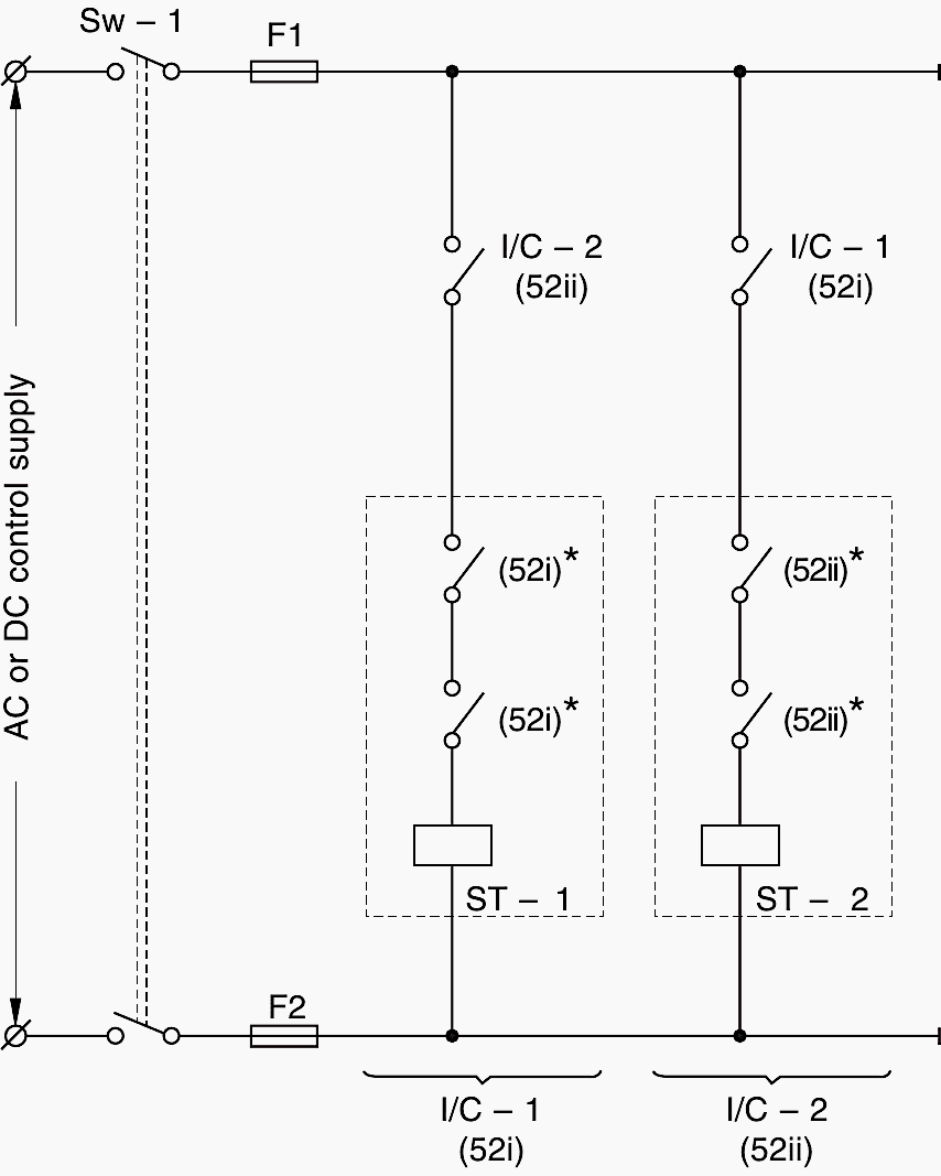
* Note: Normally 2NOs of the interrupters are wired in series to share the arc energy and enhance the contact life.
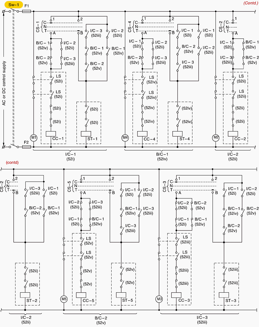
Legends details:
- Sw – 1: Control supply ON/OFF switch
- F1 – F2: Control fuses
- ST1, ST2: Shunt trip coils of breakers
- I/C: 1, 2 or 52(i, ii): Incoming sources of supplies
3.2 Scheme with two sources of supplies and a bus coupler
The logic is the same as above. In the trip circuit of each interrupter is wired the NO contacts of the other two interrupters. Obviously only two of the three interrupters can be switched at a time.
See Figure 8.
Figure 8 – Electrical interlocking scheme for manually operated breakers for two sources of supplies and a bus coupler
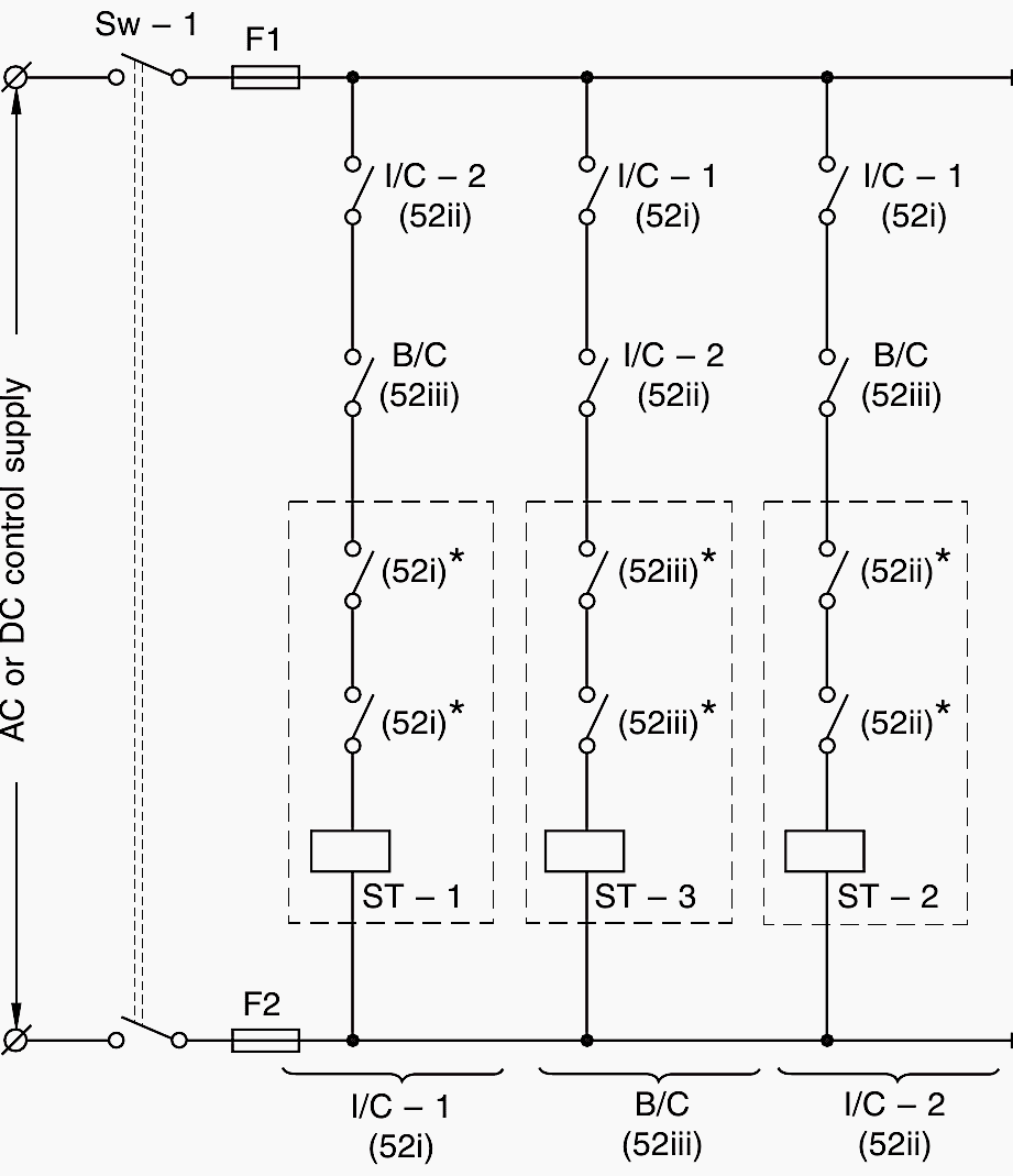
* Note: Normally 2NOs of the interrupters are wired in series to share the arc energy and enhance the contact life.
Legends details:
- Sw – 1: Control supply ON/OFF switch
- F1 – F2: Control fuses
- ST1, ST2, ST3: Shunt trip coils of breakers
- I/C – 1, 2 or 52(i, ii): Incoming sources of supplies
- B/C – 1 or 52(iii): Bus coupler
3.3 Scheme with three sources of supplies and two bus couplers
The scheme is now more complicated but the following logical approach will make it simple. See Figure 9.
(a) When I/C-1 (52i) is required to be switched
- (i) Interlocking with I/C-2 (52ii): I/C-2 (52ii) and B/C-1 (52 iv) should not be in a closed position at one time.
- (ii) Interlocking with I/C-3 (52iii): I/C-3 (52iii), B/C-1 (52iv) and B/C-2 (52v) should not all be in a closed position at one time. Refer to the control scheme for I/C-1 (52i).
(b) When I/C-2 (52ii) is required to be switched
- Interlocking with I/C-1 (52i): I/C-1 (52i) and B/C-1 (52iv) should not both be in a closed position at one time.
- Interlocking with I/C-3 (52iii): I/C-3 (52iii) and B/C-2 (52v) should not both be in a closed position at one time. Refer to the control scheme for I/C-2 (52ii).
(c) When I/C-3 (52iii) is required to be switched
- Interlocking with I/C-2 (52ii): I/C-2 (52ii) and B/C-2 (52v), should not both be in a closed position at one time.
- Interlocking with I/C-1 (52i): I/C-1 (52i), B/C-1 (52iv) and B/C-2 (52v) should not all be in a closed position at one time. Refer to the control scheme for I/C-3 (52iii).
(d) When B/C-1 (52iv) is required to be switched
- Interlocking with I/C-1 (52i) and I/C-2 (52ii): These should not be in a closed position at one time.
- Interlocking with I/C-1 (52i) and I/C–3 (52iii): I/C-1 (52i), B/C-2 (52v) and I/C-3 (52iii) should not all be in a closed position at one time. Refer to the control scheme for B/C-1 (52iv).
(e) When B/C-2 is required to be switched
- Interlocking with I/C-2 (52ii) and I/C-3 (52iii): Both should not be in a closed position at one time.
- Interlocking with I/C-1 (52i) and I/C-3 (52iii): I/C-1 (52i), B/C-1 (52iv) and I/C-3 (52iii) should not all be in a closed position at a time. Refer to the control scheme for B/C-2 (52v).
Figure 9 – Electrical interlocking scheme for manually operated breakers for three sources of supplies and two bus couplers
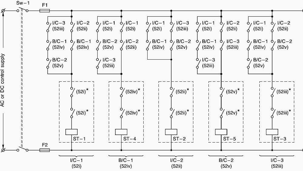
* Note! Normally 2NOs of the interrupters are wired in series to share the arc energy and enhance the contact life.
Legends details:
- Sw – 1: Control supply ON/OFF switch
- F1 – F2: Control fuses
- ST1, ST2, ST 3, ST4 and ST5: Shunt trip coils of breakers
- I/C-1,2,3 or 52(i,ii,iii): Incoming sources of supplies
- B/C-1,2 or 52(iv,v): Bus couplers.
3.4 Electrical interlocking schemes
When the interrupters are also electrically operated
Motor-operated interrupting devices are applied when the system requires remote-controlled power switching, like for an auto-reclosing scheme. With the addition of a circuit for the motor spring charging mechanism and the interrupter’s closing coil, the electrical interlocking schemes essentially stay the same. See the Figure 10.
Brief details of the electrical closing features are as follows.
Spring charging motor mechanism
The purpose of the motor is to charge the closing spring that closes the interrupter, independently of the speed and operation of the motor or of the operator when closed manually. (The interrupter can be closed manually or electrically when the spring is fully charged.)
As soon as the spring is discharged, the motor recharges it automatically to prepare it for the next operation. The motor may be fed through the same source as for the main control scheme or another source, depending upon the system design. But the source must be reliable and independent of the main power supply as far as possible (such as through a battery).
Important Note! Small interrupters and MCCBs particularly may be electrically operated through a solenoid valve.
Figure 10 – Control scheme for two electrically operated breakers and two sources of supplies
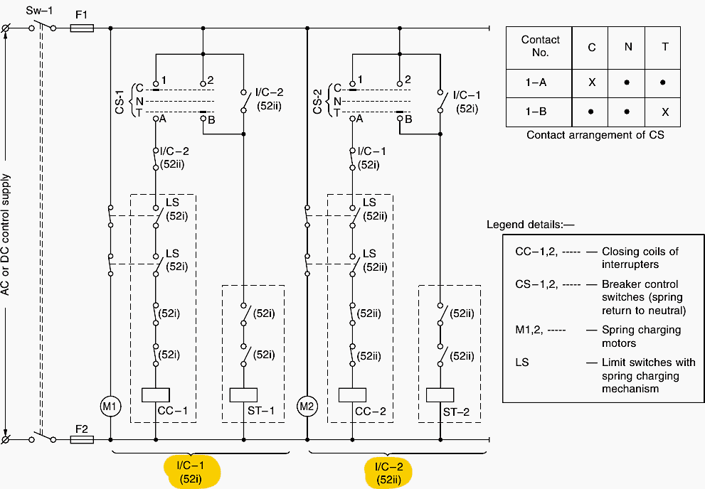
3.4.1 Limit switch (LS)
The spring charging mechanism is fitted with a limit switch, having generally 2NO and 2NC change-over contacts. The 2NC contacts are wired in series with the motor to allow it to charge the spring mechanism immediately on discharge of the spring, to prepare it for the next operation.
As soon as the spring is fully charged, the NC contacts change over to NO and cut off the supply to the motor terminals. See Figure 11 below.
The 2NO contacts of the limit switch are wired in series with the closing coil of the interrupter. As soon as the spring is fully charged these contacts change over to NC and the closing coil circuit gets ready to close.
Further Study – Mastering switchgear control circuits – AC/DC circuits and circuit breaker closing circuit
Mastering switchgear control circuits – AC/DC circuits and circuit breaker closing circuit
3.4.2 Closing coil (CC)
The charged closing spring may be released manually or electrically by energizing a closing coil as shown in the above Figure 10.
Figure 11 – Control scheme for two electrically operated breakers, a bus coupler and two sources of supplies
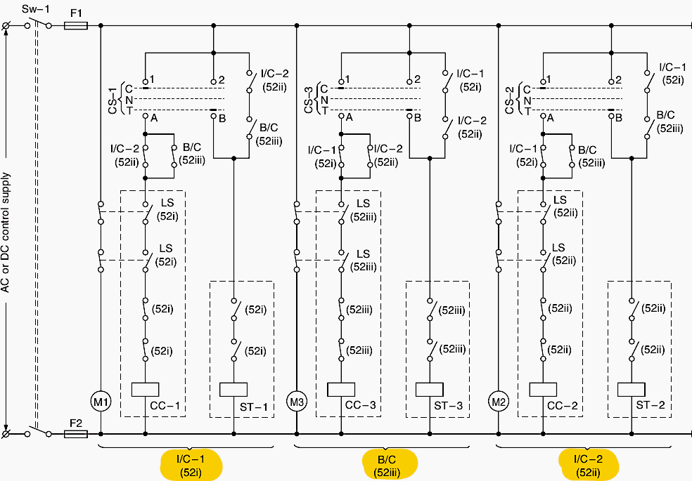
3.4.3 Breaker control switch (CS)
To close or trip the interrupter locally or remotely a breaker control switch is also wired with the closing and the shunt trip coils of the interrupter, as shown in Figure 10. The switch is a spring return type to ensure that it resumes its original (neutral) position as soon as it has carried out its job of closing or opening the interrupter.
With the above features in mind, the control logic for the various interlocking schemes becomes simple as shown in Figures 10, 11 and 12:
- Two sources of supplies: Figure 10.
- Two sources of supplies and a bus coupler: Figure 11.
- Three sources of supplies and two bus couplers: Figure 12.
Figure 12 – Control scheme for three electrically operated breakers, two bus couplers and three sources of supplies
4. Attachment (PDF)
The Basic Power Substation Theory For Students
Download: The Basic Power Substation Theory For Students (for premium members only):
Source: Switchgear and controlgear assemblies by K.C. Agrawal
Related electrical guides & articles


Edvard Csanyi
Hi, I'm an electrical engineer, programmer and founder of EEP - Electrical Engineering Portal. I worked twelve years at Schneider Electric in the position of technical support for low- and medium-voltage projects and the design of busbar trunking systems.I'm highly specialized in the design of LV/MV switchgear and low-voltage, high-power busbar trunking (<6300A) in substations, commercial buildings and industry facilities. I'm also a professional in AutoCAD programming.
Profile: Edvard Csanyi

HI,
i need two incomer and one bus coupler controller circuit drawing .