
Estimated Study Time: 27 minutes
Retrofit an old substation design
This approach assumes retrofitting and upgrading old substation secondary equipment such as intelligent electronic devices (IEDs), monitoring sensors, power apparatus, communication protocol and operating standards to improve the overall performance or reduce cost without disrupting the continuity of service.
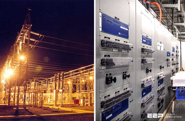 Secondary equipment you should always consider when retrofitting existing HV substation
For this purpose, a comprehensive survey of new technologies is done and the cost benefit analysis is addressed.
Two scenarios are discussed: upgrading and expanding (if possible) the old substation equipment using latest technologies. The emphasis is given to the use of wireless and optical fiber communication media when adding new equipment and using software integration of data when retrofitting existing design.
Retrofit for the substation secondary equipment
In following paragraphs, we introduce some retrofit options for the substation secondary equipment. The main functionalities of the secondary system of the substation are categorized into protection, monitoring, communication and backup& emergency control.
The retrofit strategy is split into four sections:
- Switchyard sensors
- Intelligent Electronic Devices (IEDs)
- Use of fiber optic cables
- Wireless communication
1. Switchyard monitoring devices
The main functionality of the sensors is to measure signals from primary equipment in the substation yard such as transformers, circuit breakers, power lines, etc.
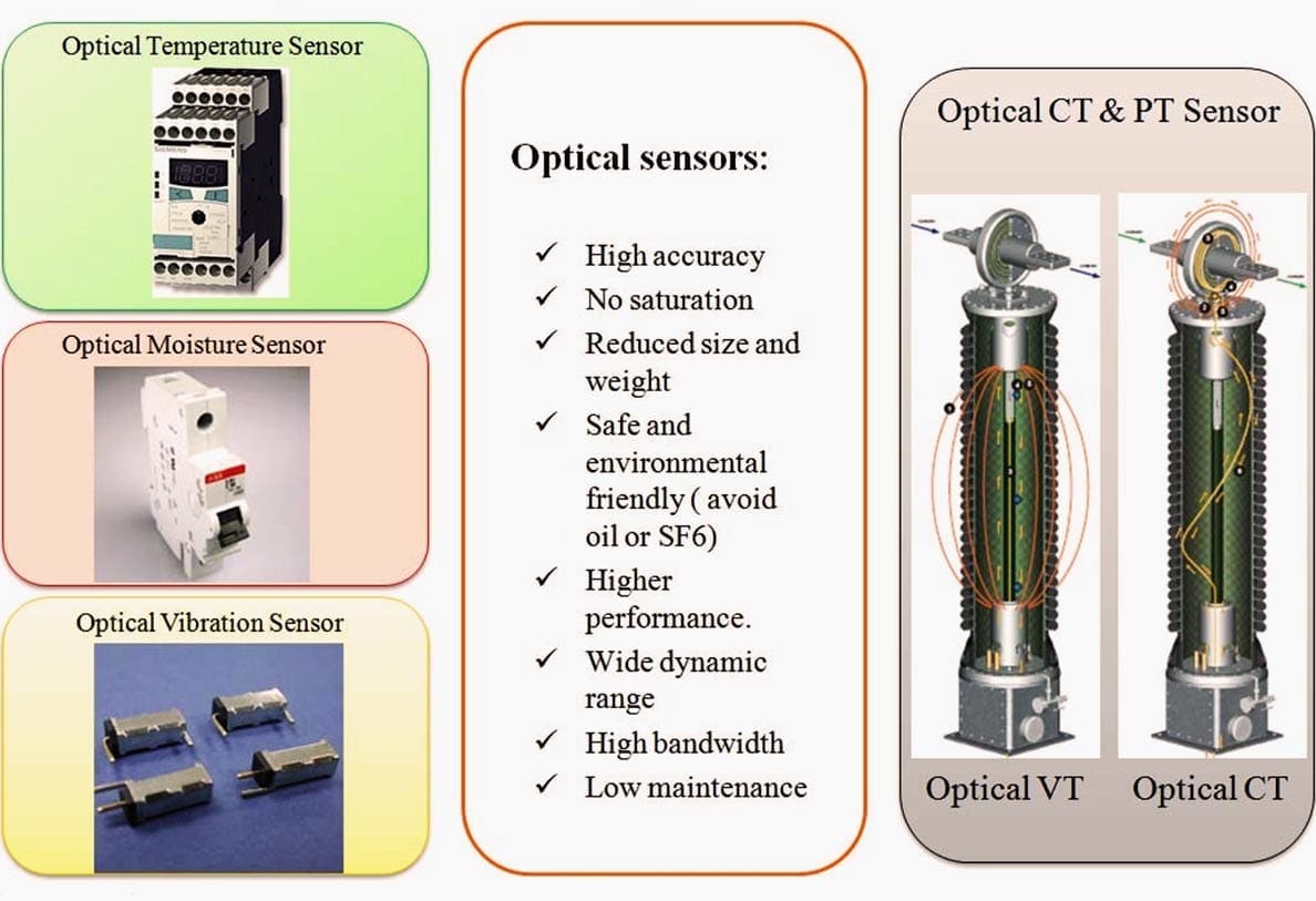
As an example, the most prominent advantages of optical fiber current and voltage sensors are high accuracy, no saturation, reduced size and weight, safe and environmental friendly (avoid oil or SF6), higher performance, wide dynamic range, high bandwidth and low maintenance (Figure 1).
1.1 Temperature sensors
It may be a new functionality for some old substations which still lack this kind of technology. Original copper-wired analog apparatus may be replaced by optical apparatus with fiber-based sensors to measure temperature.
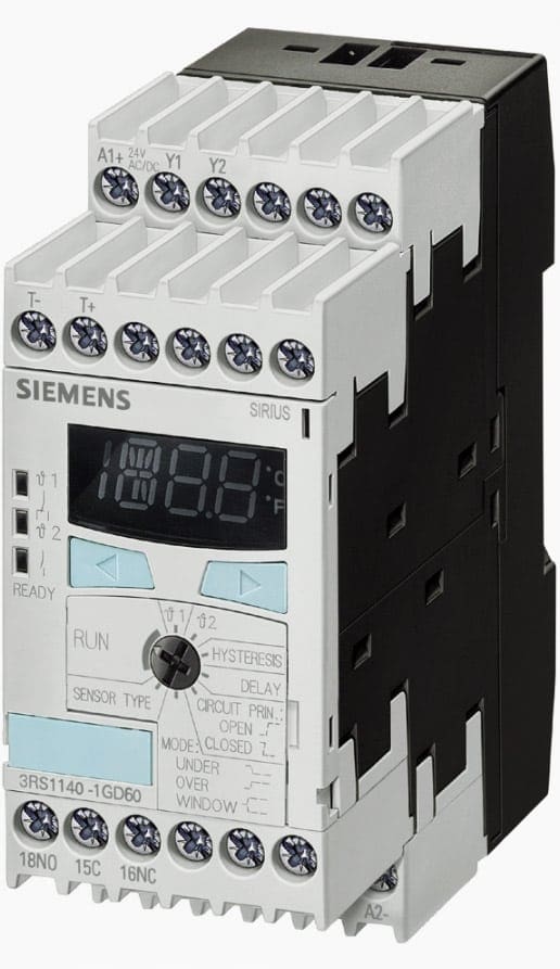
SIRIUS 3RS1 and 3RS2 have temperature monitoring relays monitor heating, air conditioning and ventilation systems just as reliably as motors – and all this with up to 3 sensors simultaneously.
Thus, the high-end analysis equipment with digital displays can be used for a broad temperature range and with different types of sensors.
1.2 Pressure sensors
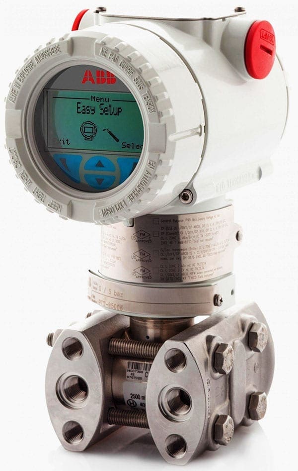
Some substations still lack this kind of sensors, and existing sensors are mostly analog. They can be replaced by an optical one such as ABB’s S266 pressure sensor.
The S266 are used in combination with 266 compact transmitter class, allowing gauge, level or absolute pressure measurements. A wide range of remote seal types are available, which allows optimum design.
1.3 Vibration sensors
A new optical technology such as Vibration Sensor Switch by Oncque Corporation, allows optical monitoring of vibration of circuit breakers and other primary equipment such as transformers switch disconnectors etc.
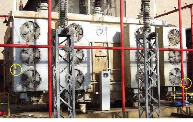
1.4 Oil and gas monitoring devices
Besides the protection of the transformers, the monitoring of the operation of transformers is essential as well. Dissolved Gas Analysis (DGA) monitoring is one of the most valuable diagnostic tools available.
It is a procedure used to assess the condition of an oil-filled transformer from an analysis of the gases dissolved in the cooling/insulating medium. It is a well established technique that is cost effective, providing essential information from a relatively simple, non-destructive test based upon oil sampling.
Existing substations are mainly using off-line and at-line methods to evaluate the oil condition of the transformer.
Table 1 – DGA monitoring methods
| Phase and its name | Definition | Advantages | Disadvantages |
| Off-line | Manual sampling and Lab. Analysis | Strict analyzing process, accurate and reliable | Long sampling interval |
| At-line | Manual sampling and in situ analysis | Immediate results analyzed | Equipment for in situ analysis required |
| On-line | Sampling continuously or discontinuously by side way | Automatic sampling by side way | Side way sampling required, temperature and pressure must fit the analyzer |
| In-line | Sensor placed at the sampling point | Located in situ real time analysis | Sensor needed to fit the measuring locale |
With laboratory analysis only, no real-time results can be obtained so as to ensure the monitoring of transformers at all time. With the at-line analysis, it is manual labor tasks that lacks the flexibility and cannot always guarantee the accuracy.
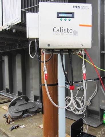
An example of such product is Morgan Schaffe DGA Calisto 9 which uses gas chromatography with proven reliable results. This is a physical method of separation in which the components to be separated are distributed between two phases, one of which is stationary (stationary phase) while the other moves in a definite direction (mobile phase).
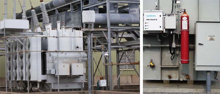
On-line and In-line DGA sensors are two new methods for transformer monitoring. Most of current substations are lacking on-line DGA monitoring devices and it can be used as a good retrofit option.
Examples of this product is TMD Smart Monitor by Siemens.
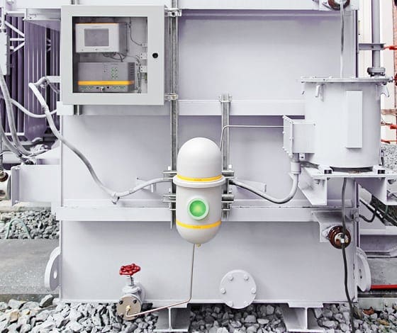
For in-line DGA monitoring, products are now being developed and put into practice, like monitoring and assessing transformer and LTC health. Monitoring the dissolved gas levels in transformer oil samples is a useful, trusted maintenance tool for assuring optimal asset health.
1.5 Current and Voltage sensors
Current transformers (CTs), Potential Transformers (PTs) or Voltage Transformers (VTs), also called instrument transformers, are used to measure current and voltage signals.
A current transformer (CT) produces a reduced current at the secondary side proportional to the current in the primary circuit, which can be used to conveniently connect measuring and recording instruments. A current transformer also galvanically isolates the measuring instruments.
Traditional current/voltage transformer, which is still widely used in power system, is based on magnetic circuits. This may create series of problems such as measured signal bandwidth limitation, magnetic saturation, etc.
However, recent trend goes in direction of developing combined fiber-optical current and electronic voltage transformer.
Combined fibre-optic-electronic current and voltage transformers are the newest technology. They combine all the advantages of two electronic transformers in one.
Their reduced size and weight compared to conventional electromagnetic transformers means that combined transformers can be installed even in small substations where there is limited space.
2. Intelligent Electronic Devices (IEDs)
Recent multifunctional Intelligent Electronic Devices (IEDs) provide higher performance, reduction in operating cost, reduction in size, increase in efficiency and improvement in robustness in the existing substations.
As an example, protection relays are widely used in all kind of substations for different purposes from individual functions, such as differential protection, distance protection, overcurrent protection, metering, monitoring, etc, to several protection, monitoring, control and user interface functions included in one box.
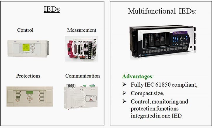
The main advantages of multifunctional IEDs are that they are fully IEC 61850 compatible, have compact size and offer various functions contained together in one design. This means reduction in size, increase in efficiency and improvement in robustness which is the main design goal.
The use of different digital simulators can help in the process of testing and evaluating the IEDs and making more informed decisions about the use of various features and selection of related settings.
Integrating multifunctional IEDs in one substation automation system can offer variety of benefits. To make sure the benefits are fully explored, engineer needs to think of new functions that can add the value to substation automation solutions.
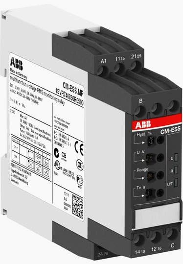
2.1 Metering and monitoring relay
ABB has a product, CM-ESS that can meter and monitor over or under voltage in single or multi-phase AC or DC system.
Multi-functional voltage metering and monitoring relay uses a multiplexer that has high speed synchronous communications, bit error correction, data management, and alarms with diagnostic at the same time.
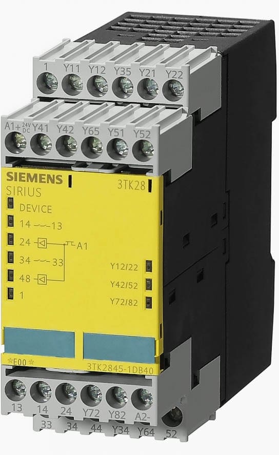
2.2 Control house safety function relay
SIEMENS’ Multi-Functional Safety Relay (Sirius 3TK2845 multi-function device) combines multiple functions of individual safety relays in a single device.
The arrangement of the functions in the diverse variants ensures that the most common applications can be realized with minimum engineering and cost expenditures.
2.3 Transmission line protection relay
Combination of different protection and protection-related functions such as line protection, auto reclosing, fault location, circuit breaker monitoring can be combined in one product.
Examples of such products are Siemens 7SD600 relay which is a numerical current differential protection relay for distribution, as well as SIPROTEC 5 7SA522 for transmission, and GE F-60 for feeder protection.
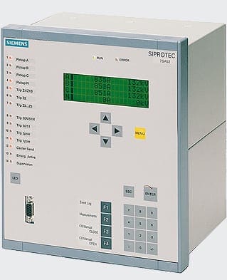
SIPROTEC 7SA522 is designed to provide fast and selective fault clearance on transmission and sub-transmission cables and overhead lines with or without series capacitor compensation. The power system star point can be solid or resistance grounded (earthed), resonant-earthed via Peterson coil or isolated.
The SIPROTEC 7SA522 is suitable for single-pole and three-pole tripping applications with and without tele (pilot) protection schemes.
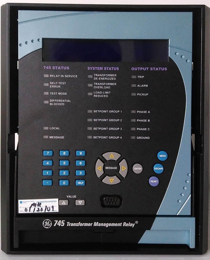
2.4 Transformer protection
High-speed, three-phase, multiple winding transformer protection system, like GE Multilin SR745 which is a three-phase, multiple winding, transformer relay intended for the primary protection and management of small, medium and large power transformers includes a full featured set of protection, I/O, data logging, and communications capabilities.
2.5 Bus protection
Comprehensive and scalable bus and breaker failure protection for LV, HV or EHV Busbars, like GE B90, features integrated protection and breaker failure for reconfigurable LV, HV or EHV multi-section busbars with up to 24 feeders.
One can use one or more B90s together to build a sophisticated protection system that can be engineered to meet the specific application requirements. The B90 performs fast and secures low impedance bus protection with sub-cycle tripping time averaging 0.75 cycles.
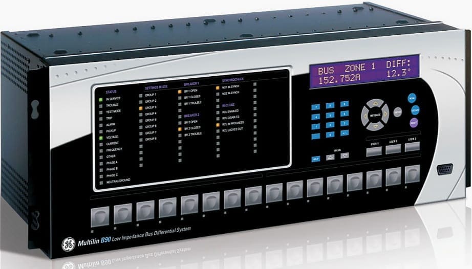
Use one B90 to protect up to 8 feeders and use three or more B90s together in a centralized phase-segregated architecture to protect up to 24 feeders. Many busbar applications, such as single, double, triple, breaker-and-a-half, with or without transfer bus, can be protected using the B90.
The B90 is ideally suited for applications where high impedance schemes are typically used.
2.6 Fault recorder
Multi-functional fault recorder can integrate many functions associated with fault recording. Such products, like the GE REASON RPV-311, are a device for the acquisition, monitoring and recording of electrical quantities in applications demanding a high level of performance and flexibility.
The RPV311 is a multifunction processing unit and has an acquisition system with 16-bit A/D D converters that provide an acquisition rate of 256 points-per-cycle synchronized by the IRIG-B signal.
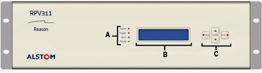
It has a high processing capability, which allows the acquisition of up to 64 analog channels and 256 digital channels divided in up to 8 acquisition modules connected by fiber-optic links. Additionally, it is able to detect IEC 61850 GOOSE messages. It allows communication through the electrical Ethernet ports and optionally has a double internal converter for optical Ethernet interfaces.
Monitoring and configuration are performed through a web interface; also, it has a human-machine interface on the front panel for displaying information. It has a MODBUS and DNP3 interface for SCADA integration.
3. Fiber optic cables
In a large substation, the cable length is around 200000 feet (17000 feet 12/C cable). The weight of copper wiring is pretty high, and sometimes creates interference problems.
In some old substations, they have been damaged substantially by rodents. The electrical substation environment has many environmental challenges to reliable and secure communications. These challenges involve high voltages, extreme temperatures, high-current faults, electromagnetic interfaces, and electrostatic discharges.
Also, no external power is required for fiber optic transceivers which are designed to work in the harsh substation environment. The reliability, performance and weight of this wiring material can affect the entire performance of the substation.
The other advantages of this technology are higher speed, longer distance of transmitting information, greater immunity to electromagnetic interferences and lower cost. Both technical and cost considerations have to be taken into account in the decision to replace the damaged copper cables with fiber-optic cables.
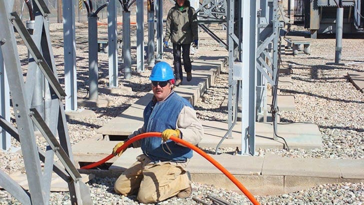
Installation of fiber optic is pretty difficult and it requires expert human resources. Also, fiber is sensitive to twist. These shortcomings should be considered when evaluating the retrofit options. The fiber optic installation is shown in Figure 15.
From Figure 16, it may be seen that the primary equipment sensors are wired over copper cables to A/D converter block and the output digital signals are multiplexed together.
Hence, each primary equipment and associated sensors use only one fiber-optic cable to transmit measurements to the control house. This saves considerable amount of wiring as the distance of primary apparatus to control house is around 1000 feet.
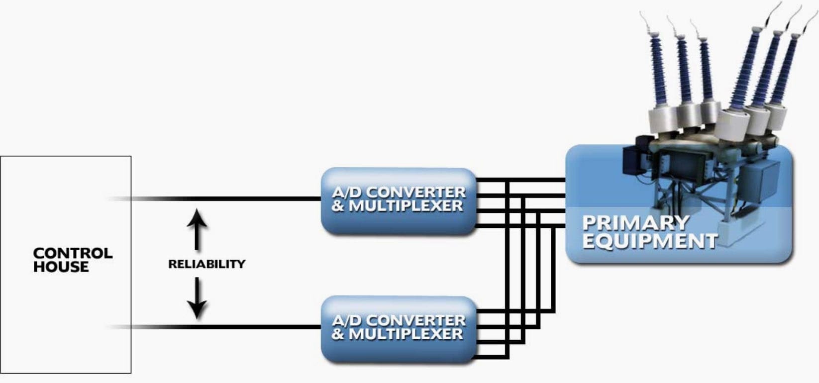
In summary the fiber-optic design reduces the wiring need to less than half, and the cost of the fiber-optic is less than copper wires for the same use and application.
The additional hardware requirements for the use of fiber-optic cable are about a few thousand dollars. By comparison the prices, considerable amount of money will be saved, and it can be easily concluded that the replacing the old wiring with fiber optic cable is economical.
4. Wireless communication
Wireless communication is another option for data transfer from substation switchyard to control house which does not require wire installation in the switchyard.
This solution is easy to install and provides compact low cost solution. Data transfer speed is not critical because data are not used in real-time control applications.
There are several technologies, which can be used for this purpose:
- Frequency Hopping Spread Spectrum (FHSS),
- ZigBee,
- WI MAX,
- wireless LAN
- etc.
Some of them are more suitable for harsh environment and short distances. Figure 17 illustrates the simple concept of wireless communication between switchyard and control house.
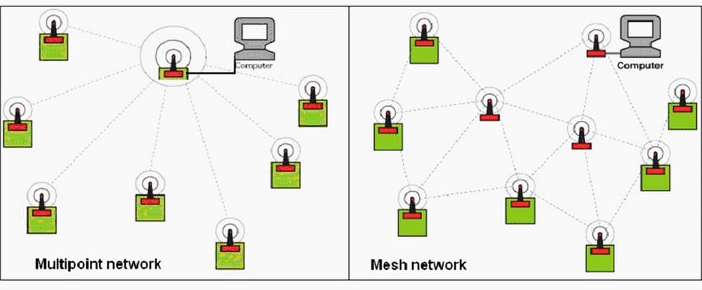
In addition, several configurations could be used for this network: Multipoint and Mesh configuration, Figure 18 shows a few most suitable options for circuit breaker monitoring communication.
Because of high level of Electromagnetic Interference (EMI) in substations, output power of transmitters should be higher than power required for normal outdoor application. Transmitter’s Equivalent Isotropically Radiated Power (EIRP) in multipoint network configuration should be around 60mW (18dBm) for 2.4GHz frequency range.
In some countries maximum allowed power is limited to 10dBm or 12dBm so gain antennas and repeaters could be used to enable longer distance communication.
Mesh network configuration requires larger number of low power transmitter, which makes it very reliable because of multiple transfer paths through the network.
Network should also have error detection and error handling mechanism. Encryption should be considered as an options but it should not overburden microprocessor of the field unit. Sometimes encryption algorithms are even implemented in wireless transceivers so that could be easily used.
Benefits of retrofit design
The benefits of retrofit of the existing substations can be summarized as follows:
- Cost reductions in operation, maintenance and service
- Prolonged equipment service life
- Higher productivity and availability of assets.
- Improving reliability, entire performance and efficiency
- Improved maintainability
- Lower installation time
- Enhanced communications
- Better utilization of data
- New functionality
- Increased cost efficiency, performance and availability of the system
The prominent advantages of replacing the original copper-wired analog sensors by optical fiber-based sensors for monitoring and metering can be listed as follows:
- High accuracy
- Higher performance
- No saturation
- Low maintenance
- Reduced size and weight, switchgear integration and potential substation size reduction
- Safety, no risk of explosion
- Environmental friendly (avoid oil or SF6)
- Wide dynamic range and high bandwidth
Wireless communication between substation switchyard and control house is easy to install and provides compact low cost solution.
Reference // The 21st Century Substation Design by Power Systems Engineering Research Center
Related electrical guides & articles


Edvard Csanyi
Hi, I'm an electrical engineer, programmer and founder of EEP - Electrical Engineering Portal. I worked twelve years at Schneider Electric in the position of technical support for low- and medium-voltage projects and the design of busbar trunking systems.I'm highly specialized in the design of LV/MV switchgear and low-voltage, high-power busbar trunking (<6300A) in substations, commercial buildings and industry facilities. I'm also a professional in AutoCAD programming.
Profile: Edvard Csanyi

Sir i need brief details about ups and central battery bank systems
Gentlemen:
Good day.- I was looking for manufacturers of Battery Bank for Transmission Line Project.
Tenders have been issued complete details would be provided in case of interest.
Rgds
Muhammad Usman Ayub
Director
R.F.Enterprises
Karachi=Pakistan
E-mail: [email protected]