
Estimated Study Time: 19 minutes
The Purpose Of Tests
Secondary injection tests are always done prior to primary injection tests. The purpose of secondary injection testing is to prove the correct operation of the protection scheme that is downstream from the inputs to the protection relay(s). Why done prior to primary injection tests? This is because the risks during initial testing to the LV side of the equipment under test are minimized.
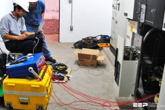
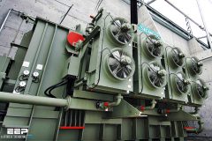
 Secondary Injection Tests For Checking The Correct Operation Of The Protection Scheme (on photo: Omicron testing device and Siemens Siprotec protection relays; credit: Omicron)
The primary (HV) side of the equipment is disconnected, so that no damage can occur. These tests and the equipment necessary to perform them are generally described in the manufacturer’s manuals for the relays, but brief details are given below for the main types of protection relays.
Let’s discuss now the following topics:
Secondary Injection Test Equipment
Test Blocks / Plugs
It is common practice to provide test blocks or test sockets in the relay circuits so that connections can readily be made to the test equipment without disturbing wiring. Test plugs of either multi-finger or single-finger design (for monitoring the current in one CT secondary circuit) are used to connect test equipment to the relay under test.
To avoid open-circuiting CT secondary terminals, it is therefore essential that CT shorting jumper links are fitted across all appropriate ‘live side’ terminals of the test plug BEFORE it is inserted.
With the test plug inserted in position, all the test circuitry can now be connected to the isolated ‘relay side’ test plug terminals.
Some modern test blocks incorporate the live-side jumper links within the block and these can be set to the ‘closed’ or ‘open’ position as appropriate, either manually prior to removing the cover and inserting the test plug, or automatically upon removal of the cover.
Removal of the cover also exposes the colour-coded face-plate of the block, clearly indicating that the protection scheme is not in service, and may also disconnect any d.c. auxiliary supplies used for powering relay tripping outputs.
Withdrawing the test plug immediately restores the connections to the main current transformers and voltage transformers and removes the test connections. Replacement of the test block cover then removes the short circuits that had been applied to the main CT secondary circuits.
Test blocks usually offer facilities for the monitoring and secondary injection testing of any power system protection scheme. The test block may be used either with a multi-fingered test plug to allow isolation and monitoring of all the selected conductor paths, or with a single finger test plug that allows the currents on individual conductors to be monitored.
A modern test block and test plugs are illustrated in presented videos.
Secondary Injection Test Sets
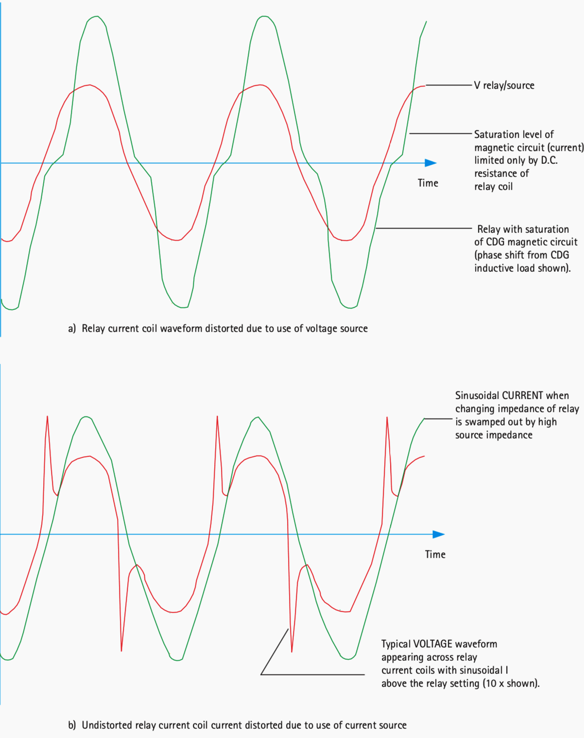
The type of the relay to be tested determines the type of equipment used to provide the secondary injection currents and voltages. Many electromechanical relays have a non-linear current coil impedance when the relay operates and this can cause the test current waveform to be distorted if the injection supply voltage is fed directly to the coil.
The presence of harmonics in the current waveform may affect the torque of electromechanical relays and give unreliable test results, so some injection test sets use an adjustable series reactance to control the current. This keeps the power dissipation small and the equipment light and compact.
Many test sets are portable and include precision ammeters and voltmeters and timing equipment. Test sets may have both voltage and current outputs.
The former are high-voltage, low current outputs for use with relay elements that require signal inputs from a VT as well as a CT. The current outputs are high-current, low voltage to connect to relay CT inputs. It is important, however, to ensure that the test set current outputs are true current sources, and hence are not affected by the load impedance of a relay element current coil.
The relay operation time may be greater than expected (never less than expected) or relay ‘chatter’ may occur. It is quite common for such errors to only be found much later, after a fault has caused major damage to equipment through failure of the primary protection to operate.
Failure investigation then shows that the reason for the primary protection to operate is an incorrectly set relay, due in turn to use of a test set with a current output consisting of a voltage-source when the relay was last tested.
Figure 1 shows typical waveforms resulting from use of test set current output that is a voltage source – the distorted relay coil current waveform gives rise to an extended operation time compared to the expected value.
Modern test sets are computer based. They comprise a PC (usually a standard laptop PC with suitable software) and a power amplifier that takes the low-level outputs from the PC and amplifies them into voltage and current signals suitable for application to the VT and CT inputs of the relay.
Digital signals to exercise the internal logic elements of the relays may also be provided.
The alarm and trip outputs of the relay are connected to digital inputs on the PC so that correct operation of the relay, including accuracy of the relay tripping characteristic can be monitored and displayed on-screen, saved for inclusion in reports generated later, or printed for an immediate record to present to the client.

Optional features may include GPS time synchronising equipment and remote-located amplifiers to facilitate testing of unit protection schemes, and digital I/O for exercising the programmable scheme logic of modern relays.
The software will normally offer options for testing, ranging from a test carried out at a particular point on the characteristic to complete determination of the tripping characteristic automatically. This feature can be helpful if there is any reason to doubt that the relay is operating correctly with the tripping characteristic specified.
Figure 3 illustrates a modern PC-based test set.

Traditional test sets use an arrangement of adjustable transformers and reactors to provide control of current and voltage without incurring high power dissipation. Some relays require adjustment of the phase between the injected voltages and currents, and so phase shifting transformers may be used.
Figure 4 shows the circuit diagram of a traditional test set suitable for overcurrent relay resting.
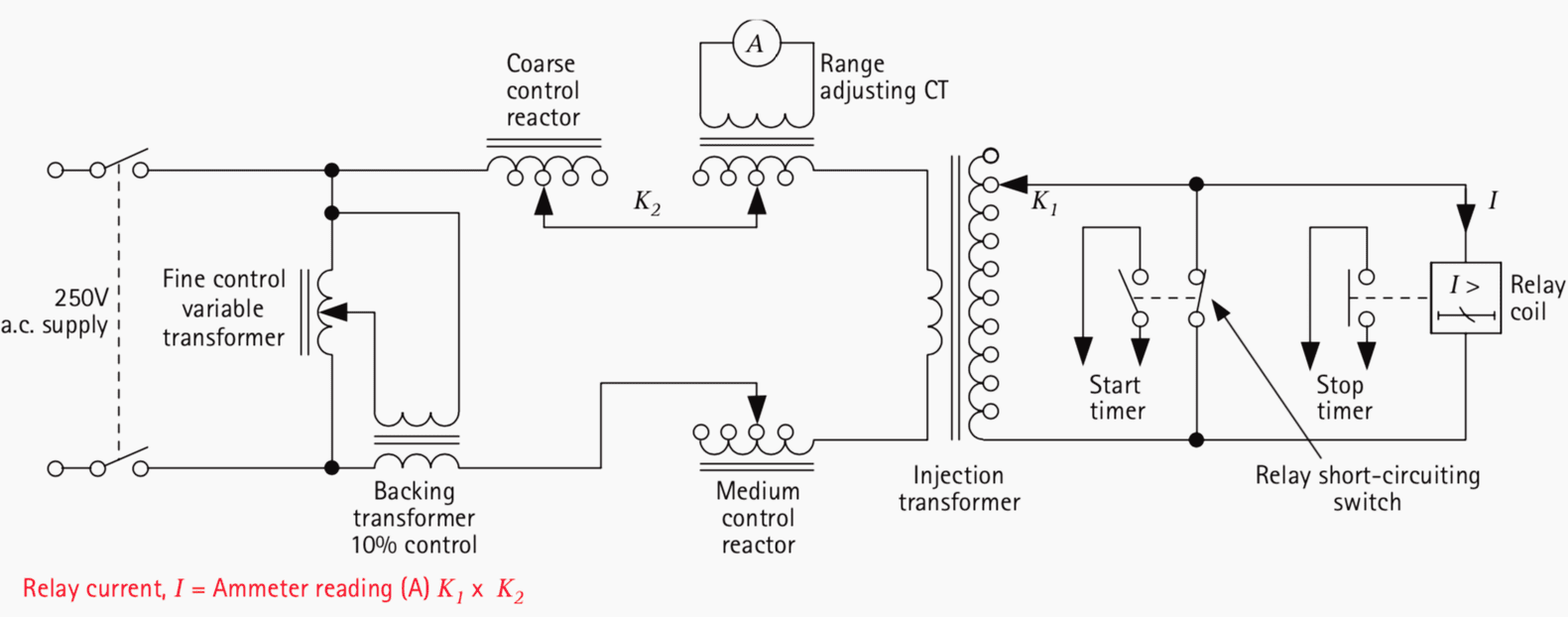
Figure 5 shows the circuit diagram for a test set for directional / distance relays. Timers are included so that the response time of the relay can be measured.

2. Secondary injection testing
The purpose of secondary injection testing is to check that the protection scheme from the relay input terminals onwards is functioning correctly with the settings specified.
The extent of testing will be largely determined by the client specification and relay technology used, and may range from a simple check of the relay characteristic at a single point to a complete verification of the tripping characteristics of the scheme, including the response to transient waveforms and harmonics and checking of relay bias characteristics. This may be important when the protection scheme includes transformers and/or generators.
The testing should include any scheme logic. If the logic is implemented using the programmable scheme logic facilities available with most digital or numerical relays, appropriate digital inputs may need to be applied and outputs monitored.
It is clear that a modern test set can facilitate such tests, leading to a reduced time required for testing.
Schemes using Digital or Numerical Relay Technology
The policy for secondary injection testing varies widely. In some cases, manufacturers recommend, and clients accept, that if a digital or numerical relay passes its’ self-test, it can be relied upon to operate at the settings used and that testing can therefore be confined to those parts of the scheme external to the relay.
In such cases, secondary injection testing is not required at all.
Another alternative is for the complete functionality of each relay to be exercised. This is rarely required with a digital or numerical relay, probably only being carried out in the event of a suspected relay malfunction.

To illustrate the results that can be obtained, Figure 6 shows the results obtained by a modern test set when determining the reach settings of a distance relay using a search technique.
Another example is the testing of the Power Swing blocking element of a distance relay. Figure 7 illustrates such a test, based on using discrete impedance points.

This kind of test may not be adequate in all cases, and test equipment may have the ability to generate the waveforms simulating a power swing and apply them to the relay (Figure 8).

Schemes using Electromechanical / Static Relay Technology
Schemes using single function electromechanical or static relays will usually require each relay to be exercised. Thus a scheme with distance and back-up overcurrent elements will require a test on each of these functions, thereby taking up more time than if a digital or numerical relay is used.
Similarly, it may be important to check the relay characteristic over a range of input currents to confirm parameters for an overcurrent relay such as:
- The minimum current that gives operation at each current setting
- The maximum current at which resetting takes place
- The operating time at suitable values of current
- The time/current curve at two or three points with the time multiplier setting TMS (Time multiplier Setting) at 1
- The resetting time at zero current with the TMS at 1
Similar considerations apply to distance and unit protection relays of these technologies.
Test Circuits for Secondary Injection Testing
The test circuits used will depend on the type of relay and test set being used. Unless the test circuits are simple and obvious, the relay commissioning manual will give details of the circuits to be used.
Commonly used test circuits are listed in the table 1 below.
When using the circuits in this reference, suitable simplifications can easily be made if digital or numerical relays are being tested, to allow for their built-in measurement capabilities – external ammeters and voltmeters may not be required.
| Test 1 | Three phase non-directional pick up and drop off accuracy over complete current setting range for both stages |
| Test 2 | Three phase directional pick up and drop off accuracy over complete RCA setting range in the forward direction, current angle sweep |
| Test 3 | Three phase directional pick up and drop off accuracy over complete RCA setting range in the reverse direction, current angle sweep |
| Test 4 | Three phase directional pick up and drop off accuracy over complete RCA setting range in the forward direction, voltage angle sweep |
| Test 5 | Three phase directional pick up and drop off accuracy over complete RCA setting range in the reverse direction, voltage angle sweep |
| Test 6 | Three phase polarising voltage threshold test |
| Test 7 | Accuracy of DT timer over complete setting range |
| Test 8 | Occuracy of IDMT curves over claimed accuracy range |
| Test 9 | Accuracy of IDMT TMS/TD |
| Test 10 | Effect of changing fault current on IDMT operating times |
| Test 11 | Minimum Pick-Up of Starts and Trips for IDMT curves |
| Test 12 | Accuracy of reset timers |
| Test 13 | Effect of any blocking signals, opto inputs, VTS, Autoreclose |
| Test 14 | Voltage polarisation memory |
All results should be carefully noted and filed for record purposes. Departures from the expected results must be thoroughly investigated and the cause determined.
After rectification of errors, all tests whose results may have been affected (even those that may have given correct results) should be repeated to ensure that the protection scheme has been implemented according to specification.
Maintenance and commissioning of protection relays
For protection relays, testing on site is common practice, whereas the other devices in many cases are sent to a laboratory for calibration, resulting in considerable efforts and costs.
Reference // Network protection and automation by Areva
Related electrical guides & articles


Edvard Csanyi
Hi, I'm an electrical engineer, programmer and founder of EEP - Electrical Engineering Portal. I worked twelve years at Schneider Electric in the position of technical support for low- and medium-voltage projects and the design of busbar trunking systems.I'm highly specialized in the design of LV/MV switchgear and low-voltage, high-power busbar trunking (<6300A) in substations, commercial buildings and industry facilities. I'm also a professional in AutoCAD programming.
Profile: Edvard Csanyi

Kindly send us a quote for conducting protection settings audit on 134 Schnider MCset feeders/Incomers, 4 RWW Engineering M&G EVOLIS, and 16 Siemens Natus Switchgear units.
Each and every article very use full. and explanation very good. Thanks for your support.
Kindly quote us on 3 phase current scits 100 secondary injection test set
Dear Sir,
Why cant we use PI Test Set to test the functionality of IDMTL Relays in tripping the Circuit Breaker?
To check transformer differential protection & line differential protection what type secondary injection kit is better ?
Dear sir please send how to transformer testing and Relay testing .full drowning and and how making kit . please sir help.8
As per table – 1 above for given tests, could you please arrange to send connection diagram for the tests?
Dear sir
Please give some article regarding synchronisation of STG in all conditions.
Well done on your good work. Please I need materials on metering, can you help me with them