
Estimated Study Time: 15 minutes
Substation power supply
The general method of supplying bulk power to buildings, factories or other complexes is by means of an MV supply, usually at 10 kV, occasionally at 6.6 kV. The installation comprises secondary distribution substation at the point of entry, with MV cables to supply subsidiary substations located near load centres.
 LV/MV Substations
Where desirable, it may be possible for the consumer to obtain two supplies from the power authority, and in special cases where loss of supply could give rise to a particular hazard (e.g. the danger to life in a hospital), the two supplies may be provided from separate sources.
In buildings containing IT equipment requiring (n+1) reliability in power supplies then dependability calculations would be undertaken to determine the Reliability, Availability, Maintainability and Safety of the bulk power supply systems.
The basic unit comprises two SF6 disconnect switches capable of making on to a fault and of breaking load current, and a fuse switch. Other units are available, assembled into various configurations. They can include circuit-breakers.
The SF6 insulated ring-main unit switching takes place in a SF6 pressurised compartment. This equipment has obvious advantages for indoor installation because of the reduced fire risk.
MV/LV distribution substations:
MV/LV distribution substations
1. General
The space requirements of a substation depend on the equipment to be housed, and on whether a new building can be erected for it or it has to be fitted into an existing building. In the latter case it may be difficult to achieve an ideal solution, but where no severe limitations are imposed the layout in Figure 1 would prove satisfactory.
This is suitable for a main 10 kV substation, also supplying local low voltage distribution, and it will be seen that it meets most of the following requirements:
Requirement #1 – There is adequate clearance around the equipment and space to withdraw circuit-breakers for maintenance.
Requirement #2 – Equipment operating at different voltages is segregated (advisable but not mandatory).
Requirement #3 – There is sufficient space for drawing in and connecting cables, and for the delivery and erection of additional switchgear: doorways are high and wide enough.
Requirement #4 – The walls can act as fire barriers. If a MV bus-section switch is included, a decision must be made as to the need for fire barrier walls between the sections. Even with oil circuit-breakers, this risk is small and many engineers disregard it.
Requirement #5 – Transformers are usually housed in open or semi-open compounds; but if an indoor location is essential, particular attention must be paid to its ventilation.
The risk of a transformer fire is extremely small: nevertheless, an oil sump (usually filled with pebbles) should be provided to trap burning oil which could escape following a fire.
The substation design described above can be said to be traditional, but in recent years, with the almost universal use of vacuum and gas-insulated switchgear from 10 kV to 15 kV, and with the growth in availability of cast-resin distribution transformers, there has been a re-think on substation design for many applications.
Over the past 30 years the concept of package substations was introduced whereby cast-resin transformers, low voltage switchgear, automatic power factor correction equipment and 10 kV switchgear is incorporated into a composite arrangement.
It should be realised that there are savings in installation costs with possible improvements in safety as mentioned in section ‘Packaged substation’ below.
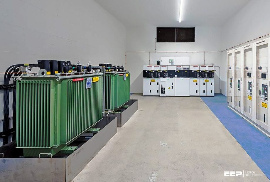
A new approach is to run 10 kV cables throughout the building to substations which incorporate the 10/0.415 kV transformer(s) as well as the 415 V switchgear.
Typical of this is the combined switchboard shown in Figure 2. In this illustration the transformer is of cast-resin type. It exhibits strong fire-resistance characteristics. This same approach can be as readily applied to industrial buildings.
To simplify the stock of spares and to ensure ready interchangeability between gear in different substations, as much standard equipment as possible should be used, even at the expense of varying fromthe ideal installation.
In general, substations should be limited to a capacity of about 2000 or 3000 kVA, with individual transformers no larger than 1500 kVA, to allow for the use of commercial LV switchgear of about 43 kA rupturing capacity.
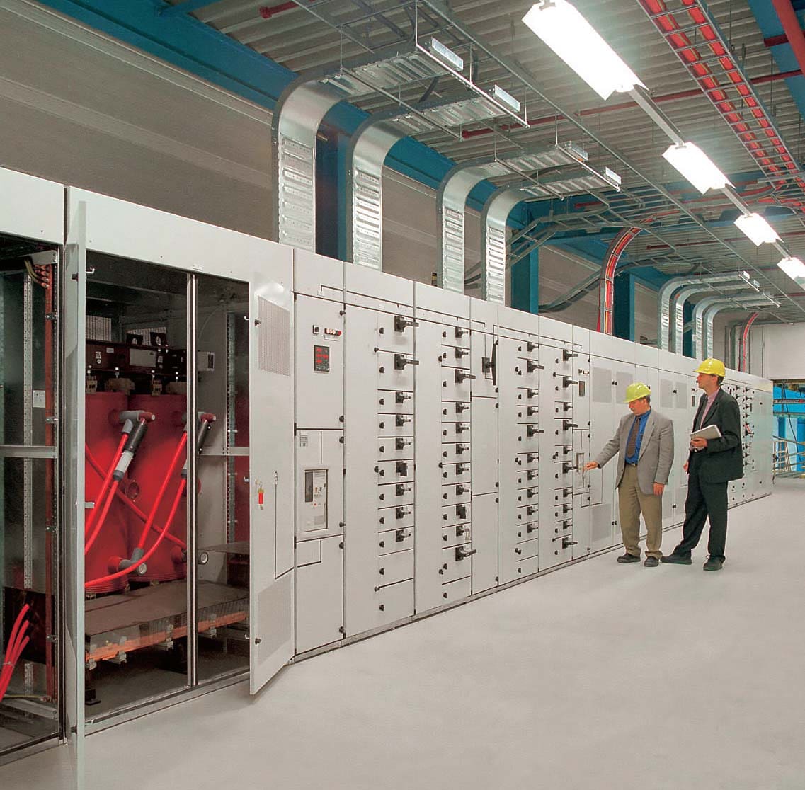
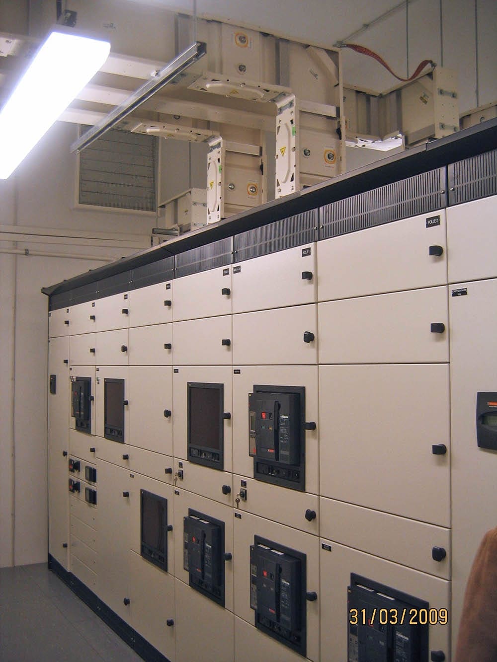
2. Low voltage equipment
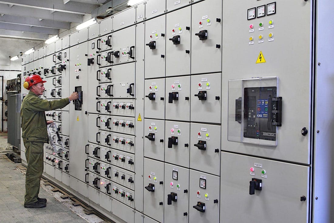
At substations the LV distribution gear consist usually of a circuit breaker for each transformer with circuit-breakers, or switches and fuses for the outgoing feeders. LV feeders are usually supplied with ammeters and often with meters to measure the energy consumption of the feeder.
In many cases maximum-demand meters are included so that this feature can be periodically monitored – a useful facility in large industrial complexes. Smart LV switchgear is now available where strategically placed voltage sensors and circuit telemetry is monitored by a PLC.
Thermal monitoring of busbars and connections using continuous infrared detectors are also available.
With duplicate cables, one may be entirely spare or both cables may share the load, provided that they are both of sufficient capacity to carry the total current independently in emergency.
Interesting reading:
Lessons I learned during installation and wiring of LV switchboard
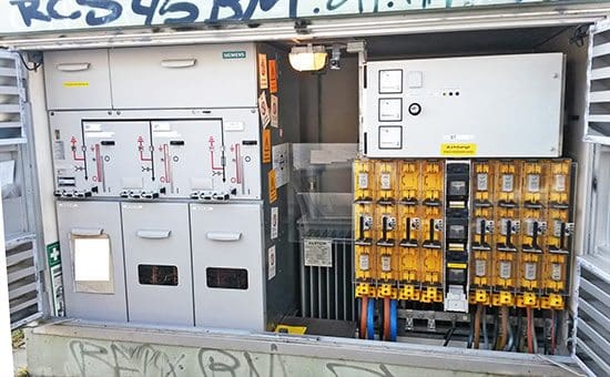
3. Packaged (compact) distribution substations
In addition to the substation designs referred above the so-called ‘packaged substation’ or ‘compact substation’ has become increasingly popular. A typical design incorporates a medium voltage SF6 switch, a cast resin transformer and fused LV outgoing ways. They are popular with supply authorities partly because of their compact construction, which makes them attractive for installation where space is at a premium.
They also require the minimum of site erection work.
They can be supplied complete with a prefabricated enclosure, often of moulded reinforced fibreglass construction, or unclad and suitable for direct installation in a building.
4. Low voltage distribution
From the substations described earlier, LV feeders run to subsidiary substations or load centres. These can include multi-motor starter boards, air-conditioning control boards, lighting and heating power distribution boards, vertical or horizontal busbars, street lighting supplies, etc.
The range of alternatives is wide and the following paragraphs outline only some of the solutions available.
4.1 Motor control starter switchboards
Large motors are usually supplied with independently separate feeders. Motor starter switchboards will probably have the facility for intelligent motor protection. This is advisable because of the heavy fluctuating load, which might otherwise cause disturbance to other plant on the same supply.
However, where a number of small or medium sized motors are in reasonable proximity, it is convenient to group the starters in a multi-motor starter panel, which often includes one or more distribution boards for lighting.
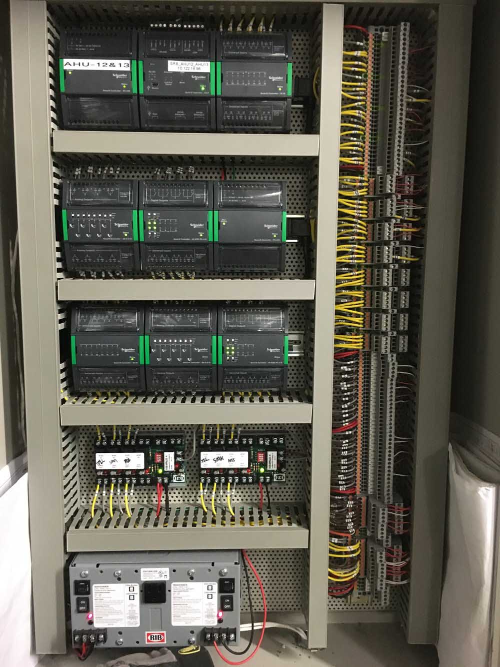
4.2 Air conditioning and ventilation control boards
Air conditioning and ventilation control boards are variants of the multi-motor starter board. As well as starters for the fans and pumps of the system, they also include the specialist control equipment needed for the automatic control of the air conditioning and ventilation.
Similar developments are found in many industries where plant process control equipment is incorporated into combined motor starter and small-power boards.
Intelligent motor control can be incorporated to monitor overload, overheating and earth faults.
4.3 Busbar trunking systems
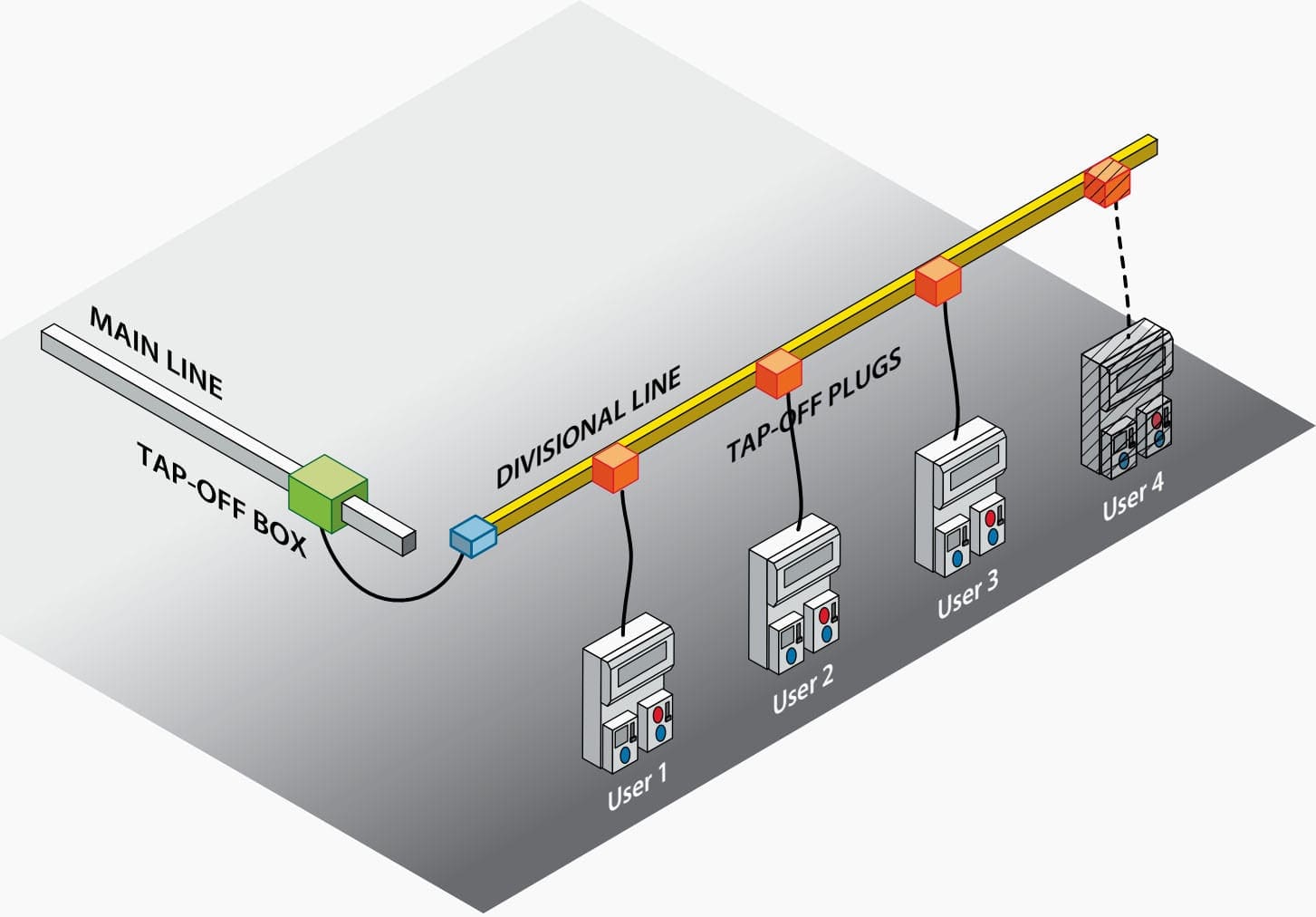
In general, wherever there are continuous rows of machine tools to be fed, an overhead busbar trunking system provides the required degree of flexibility. Used vertically, a busbar system offers simple and flexible provision of power in a high-rise building.
At the tapping points it is possible to insert a tapping box, which can be safely applied or removed with the internal busbars live. When positions of machines have to be changed or new machines installed, it is easy to insert a tapping box at the appropriate point in the run of the busbar trunking.
The maintenance cost is low, depreciation is minimal and there is a high recovery value if the trunking has to be demounted and rerun.
Earth continuity can be provided by an external link bolted between lengths of trunking, but for large ratings a separate earth conductor is necessary. No cables other than the busbars themselves may be included within the trunking.
Fire barriers are required for vertical runs, and for long runs it is advisable to provide busbar expansion joints.
From the individual fuse switch (or circuit-breaker) units on the overhead busbar, cables in conduit or flexible metallic tubing are run to the machine tools. In the case of tools with more than one motor, distribution boards can be mounted at a convenient point on the equipment.
Vertical busbars are usually run in a vertical duct within the building. A lock-proof cupboard is formed at each floor level and the distribution boards and switches are accommodated therein, with the outgoing supplies fed to meet the lighting and power needs of the floor occupants.
Where possible, it is preferable to use only one phase on each floor of the building, as this eliminates risk of voltages in excess of 240 V being encountered by personnel.
Sources:
- Electrical Engineer’s Reference Book by M.A. Laughton CEng., and D. J. Warne CEng.
- Transport and distribution inside an installation by Legrand
Related electrical guides & articles


Edvard Csanyi
Hi, I'm an electrical engineer, programmer and founder of EEP - Electrical Engineering Portal. I worked twelve years at Schneider Electric in the position of technical support for low- and medium-voltage projects and the design of busbar trunking systems.I'm highly specialized in the design of LV/MV switchgear and low-voltage, high-power busbar trunking (<6300A) in substations, commercial buildings and industry facilities. I'm also a professional in AutoCAD programming.
Profile: Edvard Csanyi

It was very helpful.Easy to execute.
Outstanding explanation, keep it up. Thanks a lot for sharing such informative stuff.
nice arrangement simple and praticable thanks
Very nice presentation ebedded with knowledge and executed field experience.would be a good option when is needed, Bye