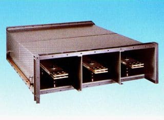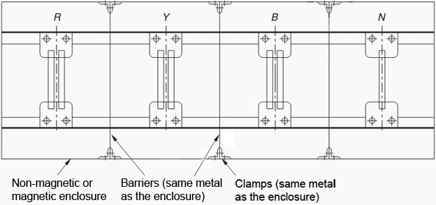
In this construction all the phases are housed in one metallic enclosure as earlier, but with a metallic barrier between each phase, as illustrated in Figure 1. The metallic barriers provide the required magnetic shielding and isolate the busbars magnetically from each other, like an isolated phase bus system (IPB). The metallic barriers transform the enclosure into somewhat like Faraday Cages.
The enclosure can be of MS or aluminium and the barriers also of the same metal as the enclosure to provide uniform distribution of field. The purpose of providing a metallic barrier is not only to shroud the phases against short-circuits but also reduce the effect of proximity of one phase on the other by arresting the magnetic field produced by the current carrying conductors within the enclosure itself.
It now operates like an enclosure with an interleaving arrangement balancing the fields produced by the conductors to a great extent and allowing only a moderate field in the space, as in an IPB system.

The enclosure losses with such an arrangement may fall in the range of 60– 65% of conductors in case of m.s. (mild steel) and 30– 35% in case of aluminium enclosures for all voltage systems 3.3– 11 kV and current ratings above 3000 A and up to 6000 A or so. Only aluminium enclosures should be preferred to minimize losses and enclosure heating.
An unbalance in the reactance is otherwise responsible for a voltage unbalance between the three phases and enhance the electrodynamic forces that may lead to a phase-to-phase fault at higher rated currents.
Applications
They are generally used for higher ratings, 3000 A and above, on all voltage systems. They are, however, preferred on an HV rather than an LV system, such as between a unit auxiliary transformer (UAT) and its switchgears and a station transformer and its switchgears as in a power-generating station and shown in Figure 13.21, for reasons of safety and also cost of an isolated phase bus system (IPB) over a segregated system.
With the availability of compact and partially isolated bus systems as discussed later, this type of bus system can be easily replaced with the non-conventional bus systems.
Nominal current ratings
These will depend upon the application. The preferred ratings may follow series R-10 of IEC 60059. They may increase to 6000 A or so depending upon the application.
SOURCE: Busbar Systems – K.C. Agrawal


