
Estimated Study Time: 15 minutes
What does distribution transformers do?
This the basic question, but it’s important to start from the scratch. Well, distribution transformers link the MV to the LV system and step down the electrical power to be distributed to the intended low-voltage level (e.g. 400 V/230 V 3AC). They are available as three-phase oil-immersed or dry-type transformers in the standardized power range 50 kVA ≤ SrT ≤ 2,500 kVA.
 4 electrical quantities you MUST fully understand to select the right cast-resin transformer (on photo: Distribution transformer type 'GEAFOL' by Siemens)
To supply power to the load centres and main loads in industrial plants, dry-type transformers according to EN 60076-11 are preferred. This technical article will take a distribution transformer type ‘GEAFOL’ as an example.
Their use has the following advantages:
- Low fire load due to design with little insulating material (less than 10 % of the weight is accounted for by the insulants),
- No special fire protection measures required (cast-resin moulding material is fire-retardant and self-extinguishing once the energy supply has been cut off),
- No risks that would make a fire more serious (e.g. toxicity risk due to release of poisonous gases in case of a fire),
- Measures to protect the ground water (e.g. oil collecting throughs or traps) are not required,
- Continuous overload capacity up to 140-150 % of the rated power due to built-on, temperature-dependently controlled radial-flow fans,
- Utilization of the continuous overload capacity as “hot standby“ redundancy to increase the supply reliability,
- No loss of service life when continuous overload capacity is used,
- No danger of impermissible switching overvoltages due to resonance excitation of the windings on switch-on and switch-off with a vacuum switch.
To select cast-resin transformers, the following electrical quantities must be determined:
- Rated voltage UrT (primary and secondary side)
- Impedance voltage at rated current urZ
- Vector group
- Rated power SrT
The appropriate values of these electrical quantities 1. to 4. depends on the use to which the transformer will be put.
1. Rated voltage UrT
The required rated voltage UrT on the primary and secondary side depends on the choice of voltage. Table 1 lists preferred values for the rated voltage of distribution transformers. It is important to note that the rated voltage of the transformer on the secondary side has values that are 5% higher than the nominal system voltage of the LV level.
This largely compensates for the internal voltage drops of the transformer when a load is applied. Distribution transformers can also be adapted to the prevailing system conditions using taps.
Table 1 – Preferred rated voltages of distribution transformers
| Rated voltage UrT of the: | |
| Primary side in kV | Secondary side in V |
| 10 (11) | 420 / 240 |
| 725 / 420 | |
| 20 (22) | 420 / 240 |
| 725 / 420 | |
Taps are additional primary-side winding terminations used to change the transformation ratio kTr. The tapping range is the range between the MV nominal system voltage UnN and the highest and lowest adjustable voltage of a winding.
The tapping range is stated as a positive or negative percentage of the nominal system voltage UnN. The transformation ratio kTr can be changed to prevent excessively low or excessively high voltages reaching the loads on the LV level due to the voltage conditions prevailing in the LV network.
See Table 2 below.
Table 2 – Matching the transformation ratio kTr to the voltage conditions in a 20/0.4kV network

Go back to Table of Contents ↑
2. Impedance voltage at rated current urZ
The impedance voltage at rated current is the voltage that is applied to the primary winding of the transformer when the rated current IrT is flowing in the short-circuited secondary winding. It is expressed as a percentage of the primary-side rated voltage.
It can be expressed as a decimal multiple of the impedance voltage at rated current urZ. The following applies:
uZ = urZ × Iload / IrT
Where:
- Iload – Load current
- IrT – Rated current of the transformer
If it is large, the transformer is not “voltage stiff“. Cast-resin transformers are manufactured with an impedance voltage at rated current of urZ = 4% and/or urZ = 6% as standard (see Table 3).
Table 3 – Standard impedance voltages at rated current in the power range of an example ‘GEAFOL’ cast-resin transformers that is relevant to industrial applications
| SrT in kVA | urz in % | |
| 250 | 4 | 6 |
| 315 | 4 | 6 |
| 400 | 4 | 6 |
| 500 | 4 | 6 |
| 630 | 4 | 6 |
| 800 | 4 | 6 |
| 1000 | 4 | 6 |
| 1250 | 6 | |
| 1600 | 6 | |
| 2000 | 6 | |
| 2500 | 6 | |
Parallel operation of distribution transformers with an impedance voltage at rated current of urZ = 4 % is largely found in networks with loads that cause unwanted power system perturbations.
These include, for example, asynchronous motors with an individual power rating that is large relative to the total power demand and welding machines.
Go back to Table of Contents ↑
3. Vector group
The vector group indicates how the phases of the two windings of a transformer are connected and the phase position of their respective voltage vectors. It consists of letters and a phase angle number.
The upper-case letter of the vector group denotes the type of connection of the primary winding; the lower-case letter, that of the secondary winding.
- “D“ or “d“ means delta connection;
- “Y“ or “y“ means star connection; and
- “Z“ or “z“ means zigzag connection.
- An additional letter “N“ or “n“ indicates that the neutral point of a Y(y) winding or Z(z) winding is brought out and therefore accessible.
In the vector group Yyn0, the primary and secondary voltages are in phase in each winding phase. In the vector groups Dyn5, Ynd5, and Yzn5, the secondary voltage lags 150 ° behind the primary voltage.
Table 4 provides a list of the most common vector groups used in three-phase transformers.
Table 4 – Preferred vector groups when using three-phase transformers

Where:
- Yyn0 – Not suitable for LV systems in which the protection against indirect contact is ensured by overcurrent protective devices and/or that contain a high proportion of single-phase loads.Because of the star-connected windings on the primary side, the current linkage is no longer balanced on the secondary side in the case of a heavily unbalanced load. The phase voltages on the secondary side can therefore vary greatly.
- Dyn5 – Preferred vector group for distribution transformers with rated powers SrT ≥ 250 kVA in industrial power systems
- YNd5 – Common vector group for generator transformers in power stations or transfer power transformers in 110 kV/MV substations
- Yzn5 – Preferred vector group of distribution transformers with rated powers SrT < 250 kVA because the zigzag connection is more favourably able to handle an unbalanced load. Unbalanced loads are especially pronounced in small three-phase systems with single-phase loads.
Both economic and technical considerations determine the choice of vector group.
For reasons concerning the insulation, the star connection is preferred at high nominal system voltages because the insulation of a star-connected winding only has to be dimensioned for 1/√3 times the line-to-line voltage.
For high load currents, on the other hand, a delta connection is more favourable. The delta winding is characterized by the fact that its winding phases are only subjected to times the phase current. This means that smaller cross-sectional areas can be used for the winding wires than in a star connection, which saves costs for materials.
For these reasons, the vector group YNd5 is used for generator transformers.
Unlike generator transformers, distribution transformers supplying a low-voltage system have to be star-connected on the secondary side. A brought-out neutral on the low-voltage side is essential so that the neutral conductor can be connected to provide the voltage for single-phase loads, which usually require 230 V.
When power is supplied to single-phase loads, however, unbalanced loads must be expected. For this reason, the necessary delta connection can only be implemented on the primary side of distribution transformers.
The preferred vector group for distribution transformers is therefore Dyn5. For use in industrial power systems, distribution transformers with vector group Dyn11 can also be considered.
Go back to Table of Contents ↑
4. Rated power SrT
The following influencing factors determine the choice of rated power SrT:
- Expense for cables and switchboards to distribute the power to the loads,
- Transformer loads optimized for losses in parallel operation (busbar interconnection of the transformers),
- Maximum power demand of the loads that form a technological and process-related unit (e.g. production or function area),
- Maximum impulse load caused by individual consumers (e.g. large asynchronous motors) or consumers operated in groups (e.g. welding machines),
- Necessary power reserve to adhere to the (n–1) principle in case of a transformer fault,
- Maximum possible short-circuit capacity of the LV operational equipment.
In accordance with the importance of each of these influencing factors, optimization calculations to determine the most economical rated transformer power must be performed.
For smaller loads per unit area (< 300 VA/m2) or higher nominal system voltages (e.g. UnN = 690 V), smaller rated powers SrT and for larger loads per unit area ( > 350 VA/m2) or lower nominal system voltages (e.g. UnN = 208 V), larger rated powers SrT are more cost-efficient.
For a power supply adjusted to the load centres, dry-type transformers from the power range 500 kVA ≤ SrT ≤ 1,250 kVA should preferably be chosen because, with large transformer units, the power reserve required to handle the (n–1) fault case increases.
Table 5 – Power calculation for parallel operation of example ‘GEAFOL’ cast-resin transformers with restrictive consideration of the short-circuit capacity
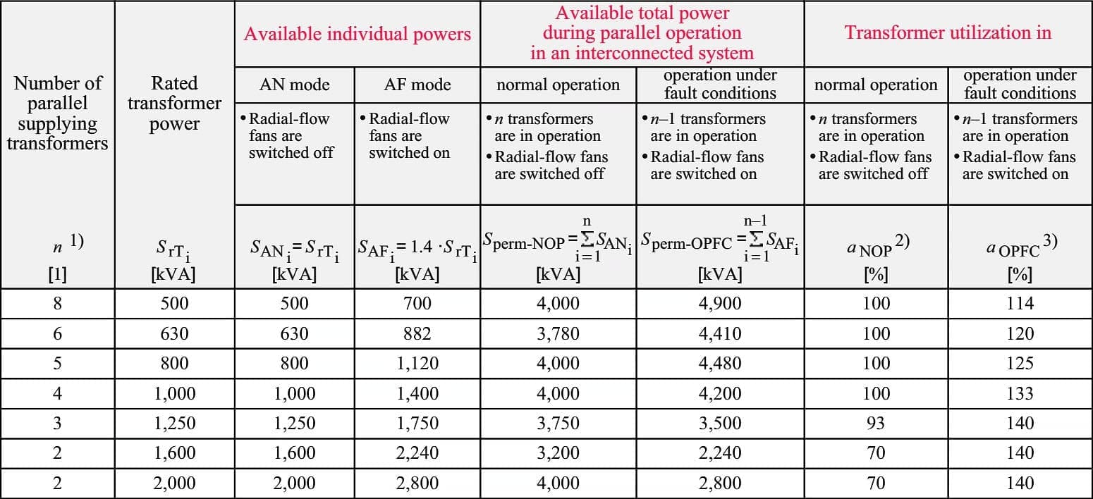
As Table 5 shows, adherence to the (n–1) principle results in poorer capacity utilization of the distribution transformers in normal operation as the rated power (SrT > 1,250 kVA) increases.
For that reason, larger transformer units (1,600 kVA ≤ SrT ≤ 2,500 kVA) should only be used to supply power to large single loads and impulse loads and where the load density is particularly high.
In an LV system without motors that contribute short-circuit current in the case of a fault, the physical limit of the short-circuit load capacity is generally reached with an installed transformer power of ∑ SrTi = 4 MVA.
Table 5 is based on this value to provide a power calculation to handle the (n–1) fault case in parallel operation of cast-resin transformers. Using the power calculation provided in Table 5, industrial LV power systems can be dimensioned according to the (n–1) criterion.
Go back to Table of Contents ↑
Sources:
- Planning Guide for Power Distribution Plants by Dr.-Ing. Hartmut Kiank and Dipl.-Ing. Wolfgang Fruth (Siemens)
Related electrical guides & articles


Edvard Csanyi
Hi, I'm an electrical engineer, programmer and founder of EEP - Electrical Engineering Portal. I worked twelve years at Schneider Electric in the position of technical support for low- and medium-voltage projects and the design of busbar trunking systems.I'm highly specialized in the design of LV/MV switchgear and low-voltage, high-power busbar trunking (<6300A) in substations, commercial buildings and industry facilities. I'm also a professional in AutoCAD programming.
Profile: Edvard Csanyi

Hello,
I am Electrical Power Engineer , I interested all information that related of electrical engineering
Hello there,
Can someone tell why WTI (Make- Perfect Controls, India) continuously showing -04.9 deg. C despite of proper WTI.
Hello there,
Can someone tell about how to change settings of WTI repeater (Make- Precimeasure, India), model no. 2247-T2.
Very happy
It is very useful to refresh and keep my electrical knowledge up-to-date.
it is a good ref- to me
thank you