
Grounding the power system neutral
In grounding the neutral of a power system, the advantages outlined will be achieved provided that proper attention is given to the impedance of the circuit from system neutral to ground. This circuit is illustrated in Figure 1 for the commonly used grounding methods. These methods are referred to as solid grounding, resistance grounding, reactance grounding, and ground-fault-neutralizer grounding.
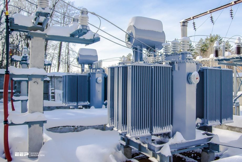 How to select grounding point(s) and how many generator or transformer neutrals to use (photo credit: Tavrida)
Note that each method is named in accordance with the nature of the external circuit from system neutral to ground. In each case, the impedance of the generator, or transformer, whose neutral is grounded is in series with the external circuit.
Characteristics of the various methods of system-neutral grounding are already discussed in many previously published articles. Application limits and guides for the various methods are outlined with reference to the following:
- Effect on development of transient overvoltages
- Damage at the point of fault due to the magnitude of ground-fault
- Application of standard relays and circuit-interrupting devices for selective ground-fault tripping
- Lightning protection
Figure 1 – System neutral circuits and methods of grounding
As already stated, we won’t deal with the above-listed grounding methods, but, instead, we will discuss how to select the system grounding point, the necessary criteria and the neutral circuit arrangement.
1. Selection Of System Grounding Point
1.1 Ground at Each Voltage Level
As illustrated in Figure 2, it is necessary to ground each voltage level to achieve the protection and advantages of neutral grounding. For example, if the 4.16 kV system in this diagram were not grounded, this level would have all the characteristics of an ungrounded system. At the same time, the 33-kV and 480-volt levels would have the characteristics of grounded-neutral systems.
Alternatively, a sufficient number of generators or transformers should be grounded to ensure at least one ground on the system at all times.
Figure 2 – Each voltage level is grounded independently
Go back to the Contents Table ↑
1.2 Ground at the Power Source and not at the Load
When a power system is grounded at the neutral of Y-connected motors, or at primaries of Y-delta step-down transformers, it is necessary to ground a number of these points simultaneously to ensure that the system will remain grounded when one or more of these loads are out of service.
Consequently, the ground-fault current may be excessively high when all grounded points are in service. Since power sources are fewer in number than loads and are less likely to be disconnected, they are preferred as grounding points, as shown in Figure 3.
Other disadvantages of grounding at the load are:
Disadvantage #1 – Standard load-centre unit substations have delta-connected primaries; therefore special transformers are required if the primaries are to be used as grounding points.
Disadvantage #2 – Since the ground-fault current is dependent on the number of feeders or grounding points in operation, it may vary widely depending on system operating conditions. This makes selective relaying more difficult and may require additional directional ground relaying to avoid false tripping of healthy feeder circuits.
Figure 3 – Ground at the source and not at the load
Go back to the Contents Table ↑
1.3 Ground Each Major Source Bus Section
When there are two or more major source bus sections, each section should have at least one grounded neutral point, since the bus-tie circuit may be open, as shown in Figure 4.
If there are two or more power sources per bus section, there should be provisions for grounding at least two sources at each section.
Figure 4 – Grounding a system consisting of two or more sections that may operate independently
Go back to the Contents Table ↑
2. Neutral Circuit Arrangement
When the method of grounding and the grounding points have been selected for a particular power system, the second question to consider is how many generator or transformer neutrals will be used for grounding and whether (1) each neutral will be connected independently to the ground or (2) a neutral bus with single ground connection will be established.
The factors involved in this determination and recommended practices are given below.
Go back to the Contents Table ↑
2.1 Single Power Source
When a power system has only one source of power (generator, or transformer), grounding of the neutral of this source may be accomplished as shown in Figure 5. Provision of a switch or circuit breaker to open the neutral circuit is not necessary because:
- Neutral circuits have practically zero potential with respect to the ground except during the short interval of a fault; hence, breakdowns are unlikely;
- It is not desirable to operate the system ungrounded by having the ground connection open while the generator or transformer is in service;
- Neutral switching equipment greatly increases the cost of grounding.
Medium voltage switches for use on 1-52kV indoor systems are predominantly used for isolation and earthing. Although the majority of these switches are air-insulated or gas-insulated (SF6), combination switches are also available, which are designed for load and fault current switching. There must be a visual indication of the switch position (by viewing the contacts or an indicator driven directly from the contacts).
Figure 5 – Grounding a single power source
Go back to the Contents Table ↑
2.2 Multiple Power Sources
2.2.1 Individual Neutral Impedances
When there are only a few generators or power transformer banks at a station, individual neutral impedances are frequently used. With this arrangement, the neutral of each generator or main transformer bank is connected directly to its neutral impedance without intervening switching equipment, as illustrated by Figures 6, 7 and 8.
No special operating instructions are required since each impedance is automatically connected whenever the corresponding power source is in use and is de-energized whenever this source is disconnected.
In the case of resistance grounding, each resistor must be rated for sufficient current to assure satisfactory relaying when operating independently. Consequently, the ground current with several resistors will be several times the minimum required for effective relaying.
When individual resistors are used, circulation of harmonic current between paralleled generators is not a problem, since the resistance limits
the circulating current to negligible values.
Figure 6 – Grounding of multiple-source system with individual neutral impedances
Figure 7 – Grounding of multiple-source system with individual neutral impedances
Figure 8 – Grounding of multiple-source system with individual neutral impedances
Go back to the Contents Table ↑
2.2.2 Neutral Bus and Switchgear
When there are more than two or three generators or power-supply transformer banks at one station, it is commonly desirable to use only one resistor. Each power source is then connected to the resistor through a neutral bus and neutral switching equipment as shown by Figure 9. This arrangement keeps the ground-fault current to a practical minimum since the ground current from the station is never greater than can be supplied through a single resistor.
It also assures the same value of ground current regardless of the number of generators or transformers iii use and simplifies ground relaying.
As shown in Figure 9, it is necessary to provide only two neutral breakers, and only one of these is closed, although all generators may be in operation. This will eliminate any circulating harmonic zero-sequence currents.
Figure 9 – Neutral grounding by means of neutral bus and switchgear
When the generator whose neutral is grounded is to be shut down, the second generator is grounded by means of its neutral breaker before the line and neutral breakers of the first one are opened. This procedure will assure that the system is grounded at all times.
In the case of multiple transformers, all neutral breakers may be normally closed because the presence of delta-connected windings (which are nearly always present on at least one side of each transformer) minimizes the circulation of harmonic currents between transformers.
Go back to the Contents Table ↑
2.3.2 Selection of Arrangement
When total ground-fault currents with several individual resistors would exceed about 4000 A, it is suggested that neutral switchgear and a single resistor be considered for resistance-grounded systems. When only one source is involved but others may be added to the station, it is suggested that space be allowed for neutral switchgear to be added if this will be necessary later.
For similar generators with reasonably equal load division, circulating currents are negligible, and it is often found practical to operate with neutral breakers of two or more generators closed. This simplifies the operating procedure and increases the assurance that the system will be grounded at all times.
Suggested reading – Practical steps in the design of a substation grounding
Go back to the Contents Table ↑
Source: Industrial Power Systems By Donald B.


Thanks MR Edvard
your subjects always reflects your deep experience in the field,thanks for the information,may Allah gives you more and more
Thanks Edvard for spreading knowledge.
I am an electrical engineer and work with wind farms and research and development in this area.
Thank you so much. Am currently an electrical engineering student in Kenya.
I normally refer to EEP in my Engineering studies. I personally appreciate this. Thanks
Good information 👍
Thanks