
Estimated Study Time: 45 minutes
VFD control, applications, schematics
This article addresses the Variable Frequency Drive (VFD) concept in several aspects that matter the most in selecting the proper VFD for applications. One of the important factors is the control type required for a given application since it is not uncommon to misselect the control type that does not provide the desired performance.
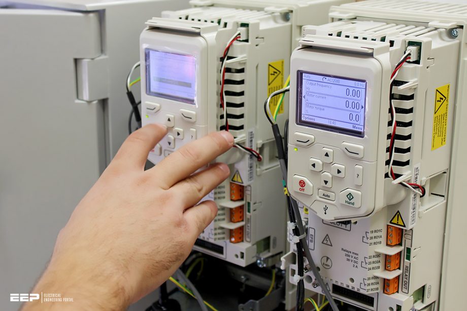 Guidelines for selecting the proper Variable Frequency Drive (VFD) for motor applications (photo credit: gibbonsgroup.co.uk)
Also, the impacts on motor applications that are expected upon utilizing VFDs are discussed along with the grounding requirements.
Often, VFDs are associated with LV applications; the MV applications are overlooked most of the time, so the main differences are highlighted. Lastly, the VFD schematics are presented to shed some light on common drawings that might be encountered.
- Introduction to VFDs
- VFD control types:
- Influence of the inverter on the insulation system
- VFD grounding
- LV and MV applications
- VFDs schematics
1. Introduction to VFDs
The simplest method to control the motor speed is to operate it at full speed, but many applications require variable speed. Many technologies had been used prior to the advent of the variable frequency drive (VFD) for speed controlling as follows: control valves, dampers, and vanes; eddy current clutches; fossil fuel engines; variable pitch sheaves; hydraulic coupling and DC solid-state control.
Initially, DC motors were used as VFDs because they could easily achieve the required speed and torque without the need for sophisticated electronics.
Figure 1 shows the block diagram of a typical three-phase VFD controller.
Figure 1 – Block diagram of a typical Variable Frequency Drive (VFD)

The function of each VFD block is as follows:
Converter
A full-wave rectifier that converts the applied AC to DC.
DC bus
Also referred to as a DC link connects the rectifier output to the input of the inverter. The DC bus functions as a filter to smooth the uneven, rippled output to ensure that the rectified output resembles as closely as possible pure DC.
Inverter
The inverter takes the filtered DC from the DC bus and converts it into a pulsating DC waveform. By controlling the output of the inverter, the pulsating DC waveform can simulate an AC waveform at different frequencies.
Figure 2 – B6 converter
Control logic
The control logic system generates the necessary pulses used to control the firing of the power semiconductor devices such as SCRs and transistors. Fairly involved control circuitry coordinates the switching of power devices, typically through a control board that dictates the firing of power components in the proper sequence.
An embedded microprocessor is used for all internal logic and decision requirements.
The number of pulses of a converter defines the number of commutations, which are used within one fundamental period, to convert AC to DC. The basic converter for a three-phase system is a B6 topology (see Figure 2). The B6 converter uses 6 commutations within one fundamental period. This results in a commutation every 60 degrees.
Table 1 – Converter pulses implementation
| Converter number of pulses | Implementation |
| 6-pulse | base on 1 B6 circuits |
| 12-pulse | base on 2 B6 circuits |
| 18-pulse | base on 3 B6 circuits |
| 24-pulse | base on 4 B6 circuits |
| 36-pulse | base on 6 B6 circuits |
Table 1 lists common converter pulse numbers. Additionally, the number of secondary terminals of the isolation transformer (if any) is proportional to the drive number of pulses as per the following formula:
xmfr#secondary × 6 = Converter#pulses
For instance, a drive with one secondary would have a 6-pulse converter whilst a drive with 4 secondaries would yield a 24-pulse converter. Figure 3 depicts a 12-pulse converter with two B6 converters and two transformer secondaries.
Related electrical guides & articles


Salem Alshahrani
Electrical engineer (BEE & Meng). Specialized in substation design, especially in LV/MV switchgears and transformers. Passionate in power system planning, analysis, and stability studies.Profile: Salem Alshahrani
