
Estimated Study Time: 12 minutes
")
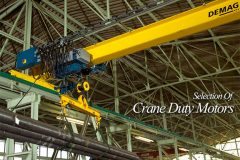
Continued from first part: Selection Of Crane Duty Motors (Part 1)
Crane Duty Motors
Types of Crane Duty Motors
Following two types of motors are widely used for crane duty applications.
- Squirrel Cage Crane Duty Motors
- Slip ring and Wound Rotor Crane Duty Motors
The crane motors are duty type rated for developing high starting torque with low starting current. The motors are designed to withstand stresses due to frequent starts/stops and reversals. Also, a rapid acceleration is achieved by high pull out torque/rotor inertia ratio.
Generally, the motors assigned duty type S3, S4 and S5 are considered for crane applications.
These motors may also be used for similar applications such as material handling, sluice operation on dams/weirs, lifts of all types and in rolling mills as auxiliary motors or wherever operating drives are required for intermittent services.
Applicable Standards
The crane duty motors should generally comply with Indian Standards provided in Table.3 below:
Table.1 Standards applicable to motors
| Indian Standard | Title | Applicability |
| IS:1231-1974 | Dimension of Three Phase Foot Mounted Induction Motors | For dimensions of motor |
| IS :2223-1983 | Dimension of Flange Mounted AC Induction Motors | For dimensions motor |
| IS:325-1996 | Three Phase Induction Motors – Specification | For specification and performance of motor |
| IS:1271-985 | Specification for Thermal Evaluation and Classification of Electrical Insulation | For insulation of stator and rotor windings |
| IS:12824-1989 | Types of Duty and Classes of Rating Assigned to rotating Electrical Machines | For duty class and assigned rating for motors |
| IS:4691-1985 | Degrees of Protection Provided by Enclosures for Rotating Electric Machines | For protection to enclosures |
| IS:6362-1995 | Designation of Methods of Cooling for Rotating Electrical Machines | For cooling of motors |
| IS:2253-1974 | Designations for Types of Construction and Mounting Arrangements of Rotating Electrical Machines | For type of mounting and frame size |
| IS:12065-1987 | Permissible Limits of Noise Levels for Rotating Electrical Machines | For noise level |
| IS:12075-1987 | Mechanical Vibration of Rotating Electrical Machines with Shaft Heights 56 mm and Higher – Measurement, Evaluation and Limits of Vibrations Severity | For vibration level |
| IS:4029-1967 | Guide for Testing of Three Phase Induction Motors | For testing of motors |
| IS :3177–1977 | Code of Practice for Electric overhead Travelling Cranes and Gantry Cranes other than Steelworks Cranes | For understanding requirements of cranes |
Standard operating conditions
In accordance with the provisions made in the applicable Indian Standard, the motors should be able to perform satisfactorily for the power supply parameters, site conditions and insulation class as provided in Table.2, unless specific parameters are furnished.
Table.2 – Power supply parameters, site conditions and insulation class for AC motors
| Supply voltage with permissible variation | 415 volts ±10%, 3 phase |
| Supply frequency with permissible variation | 50 Hz + 5% |
| Combined voltage and frequency variation | ±10% (absolute sum) |
| Unbalance | Standard motors capable to operate under unbalance supply conditions, wherein negative and zero sequence voltage components not to exceed individually 2% of positive phase sequence component |
| Ambient temperature | -10°C to 40°C |
| Altitude | Up to 1000 m |
| Humidity | Up to 100% |
| Insulation | Class “F” in Squirrel cage motors Class “F/F” for both stator and rotor in slip ring motors |
Ambient temperature
The rated output of motor specified by the vendor is generally at 40°C ambient temperature. For temperatures other than 40°C, a duration factor should be applied as indicated Table.3.
Table.2 – Ambient temperature and deration factors for AC motors
| Ambient temperature | Deration factor |
| 45°C | 0.95 |
| 50°C | 0.88 |
| 55°C | 0.83 |
| 60°C | 0.75 |
Salient technical and constructional features of crane duty motors
The technical and constructional features of crane duty motors as follows are more or less similar to that are found in the standard continuous duty motors.
- Material and construction of stator frame and end shields
- Material and construction of stator and rotor cores
- Bearings at non-drive and drive ends
- Material of construction of shaft
- Earthing to stator frame and terminal box
- Mounting of motor – foot mounted or flange mounted
- Material, construction and position of terminal box
[dropcap2]T[/dropcap2]he motor rating should be decided based on its thermal capability taking into consideration few or all factors listed hereunder as per duty requirements.
- Optimised nos. of starts and frequency of starts for all the motors should be specified for the design purpose (Starting class);
- Percentage of time during each operating cycle the motor is energised, i.e. Cyclic duty factor (CDF);
- The intermittent duty type S3, S4 or S5 should be defined correctly based on exact operational requirements of cranes. The number and type of cycle per hour should be (Duty class) should be considered;
[dropcap2]I[/dropcap2]t is vital to specify the correctly calculated “Cyclic Duty Factor” (CDF) for crane duty motors. Calculations for deriving CDF for type duty S3, S4 and S5 are given in succeeding paragraphs for reference.
[dropcap2]T[/dropcap2]he motors should have higher than normal pullout torques. As the motors are supposed to experience large no. of starts, it is necessary that the accelerating time of the system should be as small as possible. The higher pull out torque ensures rapid acceleration irrespective of drop in effective torque due to stepped rotor resistance.
Moreover for minimizing acceleration time, total inertia of the system, comprising of moment of inertia of motor plus moment of inertia of load, should be minimum. This can be achieved by keeping lower than normal rotor inertia in comparison to standard continuous duty motors.
[dropcap2]T[/dropcap2]he torque available from the motor varies as the square of the motor terminal voltage, an allowance for voltage drop in long cables, live rails and collectors must be considered. The voltage drop is significant when the motor is operated at pull out torque point, since current at this point is much higher than the rated current.
[dropcap2]T[/dropcap2]he motors should be able to withstand 1.5 times the rated current for 2 minutes without suffering damage. This feature makes the motor suitable for intermittent and severe duties experienced on the crane or similar applications.
[dropcap2]A[/dropcap2]ll 4, 6, 8, and 10 pole motors should be designed for withstanding an overspeed of 2.5 times rated synchronous speed or minimum 2000 rpm, whichever is less.
[dropcap2]T[/dropcap2]he squirrel cage motors should be provided single cylindrical shaft extension and the wound rotor (slip ring) motors should be provided double cylindrical shaft extension.
[dropcap2]T[/dropcap2]he stator and rotor windings should be impregnated with Class ‘F’ thermosetting varnish insulation. In stringent cases, Class ‘H’ insulation may also be considered.
Additionally, the rotor windings should be braced with resin-glass banding to give protection against centrifugal forces experienced by overhang during overspeed and frequent reversals. Gel-coat may be painted on the winding overhang for better consolidation and protection from vibration.
[dropcap2]S[/dropcap2]ize of the terminal box should be adequate for to facilitate splitting of power cables cores and terminate comfortably. In slip ring motors, the cables for main power supply and from slip rings are usually accommodated in the same terminal box for simplifying wiring and maintenance.
Hence in case of slip ring as well as squirrel cage motors, if required, the cable box size may be increased by providing an attachment of cable splitter box (generally of trapezoidal shape) to the main terminal box.
[dropcap2]T[/dropcap2]he rotors of squirrel cage and wound rotor motors should be dynamically balanced to ensure lowest possible vibration.
[dropcap2]I[/dropcap2]t should be preferred to use the metallic cooling fans in the wound rotor motors. PVC or plastic fans are likely to be deformed due to high temperature in housing due to slip rings and get damaged.
[dropcap2]A[/dropcap2]s the motor would generate more heat due to intermittent switching operations, the painting should be heat resistant, specifically able to withstand higher temperatures.
[dropcap2]T[/dropcap2]he standard crane duty motors should be provided IP55 Degree of protection as per IS:4691. The cooling code of motor should be IC411 as per IS:6362.
[dropcap2]T[/dropcap2]he insulation resistance of the slip-ring unit should be high enough ensuring minimum wear and breakdown. The brush holders, made as a complete unit, should be easily replaceable. The slip-ring should be large enough to encounter starting currents and for proper installation of brushes in slip ring motors.
For higher rated would rotor motors, separate disc should be provide between the slip-ring and rotor windings to prevent ingress of carbon dust from brushes into windings.
Will be continued in 2 days…
References:
- Efficient Electric Motor Systems Handbook, by Todd Litmann
- IS:12824-1989; Types of Duty and Classes of Rating Assigned to Rotating Electrical Machines
- The Technical Literature of Indian Motor Manufacturers
Related electrical guides & articles


Ashok Parikh
Working as Electrical Engineering Consultant located at Vadodara, India providing System Design & Engineering services to various industries, possessing 40 years of experience in diversified industries and consultancy.Profile: Ashok Parikh

Sir, it is not possible to provide technical specifications for the motor based on brief data given. I request you to go through all parts of article and draw specifications containing minimum data. Alternatively, you may call some manufacture at site. He would be able to give you detailed specifications and price.
We require LT motor of tongue hoisting application of following specification-
“MF13Z,2.5/15kW,14/32Amp”.
Please give details of above specification and estimated price for our procurement
Thanx
(Abakasa Behera) Dy General Manager, Steel Melting Shop-II
Steel Authority India Limited, Rourkela Stee Plant, Rourkela
Mob No-8895500245
Very informative. This is very helpful information for choosing the right duty crane motor.
The brush holders, made as a complete unit, should be easily replaceable
moteurs électriques de haute efficacité conçus pour répondre aux normes d’efficacité énergétique les plus élevées