
Estimated Study Time: 12 minutes
Continued from first part: Selection of Induction Motors for Industrial Applications (part 2)
Design Considerations (cont.)
Different Rotor Classes
The different rotor class, i.e. KL7, KL10, KL13, KL16, KLp, etc. are available in case of the motor to fulfil the functional torque requirements of the driven equipment. The rotor classes indicate against what quantum of the load torque the motor would be able to start easily.
The motor with KL10 class of rotor, when started direct-on-line, would accelerate safely to its rated speed against the load torque of 100 % of its rated torque. Similarly, the motor with KL16 class of rotor would be capable of starting against the load torque of 160 % of its rated torque.
Though, KL10 class rotor could take maximum starting torque up to 180 % of the full load torque, and for KL16 class, it could go up to 200 %, but for very minimum time exerting more stress to the rotor.
It is therefore essential to obtain the technical data for the torque requirement of driven equipment during starting and incorporate in the specification so that the motor of correct rotor class will be installed.
Constructional features of motor
Based on the application requirements, the constructional features of the motor are to be selected as follows:
Mounting Arrangement
Different types of mounting arrangement for the motors are Horizontal foot mounted (B3), Horizontal flange mounted (B5), Flange-cum-foot mounted (B3/B5), Vertical flange mounted with shaft downwards (V3), etc and so on.
It is important to specify correct mounting arrangement for satisfactory installation of motor and its coupling with the driven equipment. Details of driven equipment may also be furnished if desired by the motor vendor.
Enclosures
The enclosures are classified under two categories as follows. It is selected based on the specific application and location of the motor.
| Open Type | Totally Enclosed Type |
| 1. Screen protected drip proof (SPDP) | 1. Totally enclosed fan cooled (TEFC) |
| 2. Splash waterproof | 2. Totally enclosed surface cooled |
| 3. Pipe ventilated | 3. Totally enclosed pipe ventilated |
| 4. Weather protected | 4. Hose and splash proof |
| 5. Increased safety motor with enclosure ‘e’ for hazardous areas | |
| 6. Totally enclosed for marine applications |
Frame size

The frame size of the motor is to be selected considering ambient conditions and environment in surroundings, where it is to be installed.
If the ambient temperature is expected to be abnormally high, the motor with one higher frame size for the same rating provides better services due to availability of more cooling surface area due to higher frame size. This factor is thus related to location of the motor.
Mechanical design features
Coupling Arrangement with Load

It is necessary to mention whether the motor is to be directly coupled with the driven equipment, or coupled through a belt/chain drive, or gearbox.
For belt-drives, the motor shaft diameter and length depend on the type of belt and pulley, as the standard shaft length suitable for flat belt may not be suitable for V-belt drive and width of pulley. It is necessary to specify the shaft extension requirement.
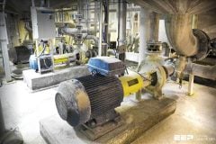
Type of Driven Equipment
For better selection of motor, it is necessary to specify the type of driven equipment, viz., centrifugal pump, compressor, blower, bowl mill, conveyor drive, etc.
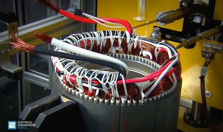
The design of windings would greatly depend on this technical data.
Terminal Box

The size of cable with number of cores should be specified so as to enable the motor manufacturer to provide correct type and size of cable terminal box. When a number of parallel cables are to be terminated, as in case of star-delta started motor, a special terminal box with a modified arrangement may be specified to facilitate the cable termination.
If required, the cable splitter box should also be specified along with the main terminal box for facilitating splitting of cable cores before termination.
Where the space heater is provided in the motor, itis desirable that the leads of space heater are brought out in a separate terminal box so as to avoid unnecessary congestion of cables in the main terminal box.
Moreover, it is essential to specify whether the terminal box should be located on side or on the top of the motor considering anticipated encroachments at site due to structures, pipelines, etc. around location of motor. Depending on the site location, it may be necessary to specify Degree of Protection required for the terminal box.
It is general practice to maintain same Degree of Protection for the motor and terminal box.
Earthing Terminals
In accordance with the Indian standard specification, two separate and distinct earthing terminals should be essentially provided on the body of the motor and one earthing terminal should be provided internal in the cable termination box is to be provided.
Additionally, one earthing terminal may also be provided on either one side of the terminal box housing or internal in the terminal box housing for enhancing overall safety of the equipment.
Location data

It is essential to include all the possible details of location and surroundings in the technical specification.
Corrosive chemical vapours attacks not only the motor winding insulation, but also the housing, stator laminations, rotor, shaft and bearings. For the motors working in the corrosive areas, the winding should be applied a specific varnished impregnation treatment, anti-acidic treatment and overhangs should be applied with epoxy based varnish.
Corrosion to metal body is prevented by applying epoxy based resin paint.
Service factor or overload capacity
The service factor of a motor indicates how much it could be overloaded without immediately failing. Generally, the motors are designed with 1.15 service factor with the development of high quality insulating materials that can withstand higher temperatures.
Although the motors operating between their full load rating and their service factor rating do not fail immediately, their service life certainly becomes shorter.
Hence, it is best to avoid designing of motors to operate with overload except for short time duration, even if permitted by the service factor. A high service factor can be used as an indication of a high quality, more reliable motor.
Conclusion
Effort made in technical article covers as many factors for selection of motor as possible, through the subject is vast. The complete technical specification would greatly facilitate the motor vendor to propose a type of motor required for a specific application.
Effective selection and application of modern day electric motors require a thorough technical and practical knowledge of basics of rotating machines as well as an in-depth awareness of the latest technical developments via continuous contact.
Operating conditions such as duty cycle, number of starts, ambient conditions, and data for location, environment, driven equipment, etc. are important considerations for the motor efficiency and reliability. It is also imperative to seek advice of the motor manufacturer many a times if motor will be operated under any unusual service conditions to support the selection procedure.

It can also be seen from the above discussion that most of the technical requirements are interwoven and closely related with each other. Consideration of one factor may affect the other factor and hence it is important to adopt an integrated approach to the total specification.
Finally, the number of specific requirements is going to raise the cost of the motor.
For example, the initial cost of high efficiency motor will be more, depending on design and specific material aspects, but the consistent lower operating cost due to less drawl of power will prove economically beneficial in a long run. Besides considering various general design features as mentioned above, the specific requirements in view of abnormal site conditions and application requirements must be considered and brought out in the purchase specification.
The extra cost, required to be incurred for some specific features, would simplify the maintenance to such an extent that the repayment would be in a shortest duration with reduced outage of the motors.
Last but not least, the selection and application of electric motors has become more complex than ever before because of the emergence of high efficiency and premium efficiency (PE) motors as a part of continuous process of technical developments. As a result, one must extremely careful look to any application of the electric motor.
Related electrical guides & articles


Ashok Parikh
Working as Electrical Engineering Consultant located at Vadodara, India providing System Design & Engineering services to various industries, possessing 40 years of experience in diversified industries and consultancy.Profile: Ashok Parikh
