
Estimated Study Time: 5 minutes
Dependance On Installation Site
The selection of number of cable cores basically depends on the type of system where it is going to be installed.
Generally we have two types of systems:
- A perfectly balanced system and
- A system with some degree of unbalance (or Unbalanced System).
Generally cable sizing includes below parameters:
- Cable installation conditions and the load it will carry
- Continuous current rating of the cable
- Voltage drop and short circuit considerations
- Earth fault loop impedance
Here, I am going to describe that how the number of cores can be selected.
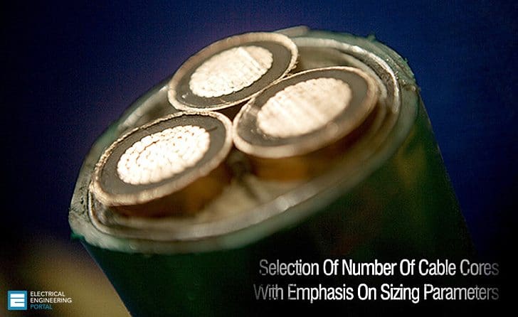
3-Core Cables
These cables are used generally for a perfect balanced 3-phase system. When the currents on the 3-live wires of a 3-phase system are equal and at an exact 120° phase angle, then the system is said to be balanced. The 3-phase loads are identical in all respects with no need of a neutral conductor.
3.5-Core Cables
A 3-phase system may have a neutral wire. This wire allows the 3-phase system to be used at higher voltages while it will still support lower voltage single phase loads.
It is not likely in such cases that the loads will be identical, so the neutral will carry the out-of-balance current of the system. The greater the degree of imbalance, the larger the neutral current.

When there is some degree of unbalance and the amount of fault current is very small, then 3.5 core cables are used. In these types of cables, a neutral of reduced cross section as compared to the 3-main conductors is used, which is used to carry the small amount of unbalanced currents.
4-Core Cables
When there is severe out-of-balance conditions, the amount of fault current will raise to a very high level. Generally in the case of linear loads, the neutral only carries the current due to imbalance between the phases.

The non-linear loads such as switch-mode power supplies, computers, office equipment, lamp ballasts and transformers on low loads produce third order harmonic currents (Definition of Harmonics and Their Origin) which are in the phase of all the supply phases.
These currents do not cancel at the star point of a three-phase system as do normal frequency currents, but add up, so that the neutral carries very heavy third harmonic currents.
5 and 6-Core Cables
Some conditions may arrive when the amount of fault (neutral) current becomes very large than the phase currents. When the load concerned to this type of situation is fed through a multi-core cable, it is necessary to use a 5-Core or 6-Core Cable.

In this condition, two (or three) conductors can be used in parallel formation to carry the high amount of generated unbalanced currents.
Related electrical guides & articles


Chirag Singhal
Completed my B.Tech in Electrical & Electronics Engineering from UPTU (Lucknow). A competent engineer with 2 Years of experience in designing electrical systems’ components to required specifications focusing on economy, safety, reliability, quality and sustainability. Strong ability to work and communicate effectively with multidisciplinary team comprised of engineering, technical, field and business support units.Profile: Chirag Singhal

Please , i want answers to these 3 questions :-
1) Why must MV & HV cable insulation done as a co extrusion and not one after the other ?
2) Why is co extrusion always done at a height ?
3) why are MV cables in 1 or 3 cores and never in 4 cores ??
1C X 1.5mm Sq. Cable , 1P X 1.5 Mm Sq. Cable , 1T X 1.5mm Sq. Cable (Please Tell Me Meaning Of 1C, 1P & 1T) THANKS
Please Reply asap.
I want to request on quotation about cable, please email me as soon as possible as a urgent. thank you
This is a goos site to have second thought
Hello,I have question about cable size file. In part of No of cable/tray, must I enter the number of cable per phase in every tray?what is the meaning of No.of runs of selected cable?
Kindly tell some think about safety features in 3 Core and 4 Core and its difference.
For a main incomer of 415V do i use 4C or 4x1C cable?
Thanks
sir,
i have a doubt, that if i run same dc 690 v in 3 cores of the 3 core cable then what will the problem. please help me.thanks in advance
I have an enquiry . to run 75 Hp motor ( 70+3+5) 4 nos. and 45 Hp 2 nos. from 500 KVA Generator . at distance From Generator 1000 m. suggest me what type of armored cable ,size and flexible cable require . all is 5 core.
i have a doubt, how to calculate the cable core and which cable is suitable for 3-phase system 415V with 50KW power rating. And also with dimensions which cable is preferable for industrial and household purpose.
sir,
i have doubt.
current rating of 4 core AYFY CABLE , aluminium conductor is 51amp at air. from current rating table,
it means each core can carry 51 amp ya ??
Actually each core will carry a slightly higher amount of current than what you have specified in the query. But when all the 4-Cores are laid up together to form a complete 4-Core Cable, the current is reduced due to heat dissipation effect due to mutual heat generation.
Dear sir,
I have an enquiry about the main factors when to chose a cable like the calculation of load, current, etc.
So, Can you please briefly explain the mathematical calculation.
The current calculation depends upon the load current requirement of the system. Once the load MVA / KVA is known, you can calculate the amount of current flowing through the load by Power- Ampere relationship. BY knowing the current value, no. of cores & cross sectional area of the cable can be determined by the Standard draft of current ratings as per IS: 1554-I or IS: 7098-I. In the draft itself, various derating factors are specified for the laying conditions of cables.
Dear Sir,
Actually i have 1 doubt.can i use 1core 50sqmm cable instead of 3cX50sqmm.if i use that what are the disadvantages or advantages.please clarify my doubt
Yes. u can use 1 core 50 sqmm cable for each phase instead of 3cx50 sqmm. the advantage is current carrying capacity and withstand capacity will be higher and disadvantages are cost ineffective and more space required.
In your post you have talked about “cable installation conditions” being one of the factors that determines the type of cable to be installed. Could you expand on this. What are the conditions.
Hey Anshuman,
There are various conditions of cable installations which are defined in the respective Current rating drafts issued by BIS & IEC for all sorts of PVC & XLPE insulated cables. Some of them are ambient air & ground temperature, soil thermal resistivity in which the cable is going to be laid, the depth of laying etc. Keeping in mind all the defined conditions, derating factors are applied which in turn affect the net current carrying capacity of the cables.
HI….
CAN YOU GIVE A BRIEF IDEA ABOUT THE USE OF CONTROL CABLE SELECTION CRITERIA.
Hey Amit,
As far as your query is concerned, I would like to clear the fact that generally control cables require very little power& they are generally used to carry intermittent control signals. In this way, they are very much different from the power cables as the later are used to carry very high amount of currents during their operation. Hence, current loading factor is not the deciding criteria for the control cables.
Control cables are generally subjected to rather severe environmental conditions such as High ambient temperature conditions (like boilers, steam lines etc.), exposures to oils, alkalies, solvents and other chemical hazardous areas (like petroleum, steel, pulp, paper & cement plants). Moreover the voltage level of control circuits ranges anywhere between milivolts up to several hundred volts.
Hence, the primary criteria that is applied for the selection of control cables are the voltage levels & environmental conditions. These conditions are very much important to scrutinize as the electrical considerations.
Nice, good article, with useful information.