Transformers in parallel operation
Calculating selectivity between incoming low voltage feeders connected in parallel is never an easy task. In parallel operation of two, three and more transformers on a common busbar, the partial short-circuit currents flowing in the individual incoming feeders add up to the total short-circuit current in a faulty feeder in which a disturbance has occurred.
This total short-circuit current is the basis for the current scale in the grading diagram.
Using the current scale based on the total short-circuit current provides more favourable selectivity conditions for all protective devices downstream of the incoming feeder circuit-breakers. This applies to all types of fault.
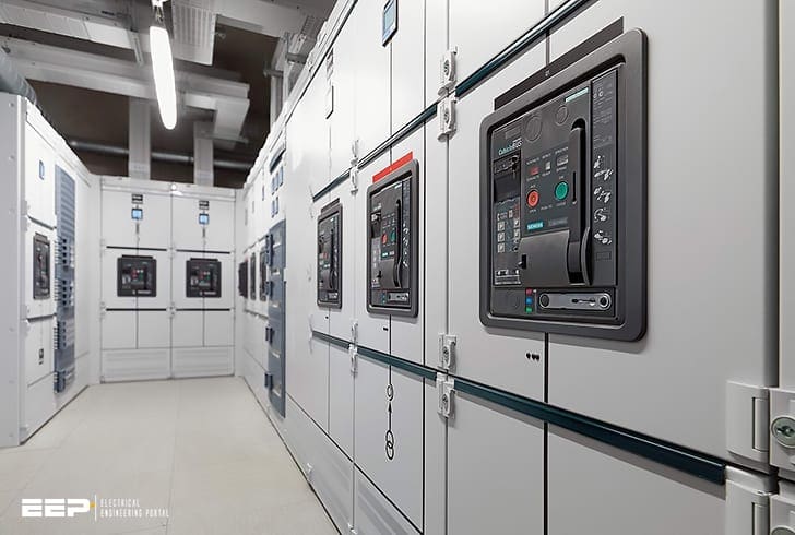
Let’s see three cases of achieving selectivity between incoming circuit breakers connected in parallel. Breakers are Siemens’s air type 3WL. If you are not familiar with this breaker, take a look at the short introduction here.
- Two identical incoming feeders
- Three identical incoming feeders
- Incoming feeders connected in parallel through bus coupler circuit-breakers
1. Two identical incoming feeders
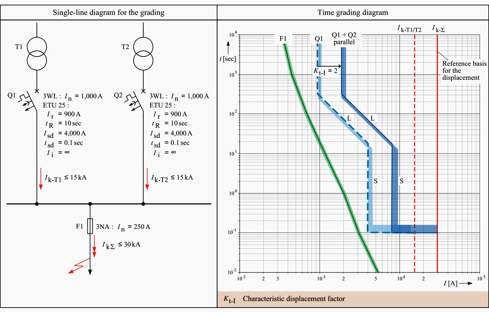
Figure 1 details the distribution of short-circuit currents in case of a fault on an outgoing feeder with two parallel-connected transformers of the same power rating and the same length of incoming feeder cables.
The total short-circuit current IkΣ flowing through fuse F1 is composed of the partial short-circuit currents Ik-T1 and Ik-T2.
This shift results in both time selectivity and an additional gain in current selectivity (see Figure 1).

If the incoming and outgoing feeders are arranged and located asymmetrically on the busbar, the distribution of the short-circuit current is different depending on the impedance ratio of the transformers and incoming feeders.
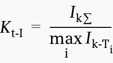
For the asymmetrical fault current distribution that usually occurs in practice, the characteristic displacement factor Kt-I must be calculated as follows:

2. Three identical incoming feeders
An even better current selectivity is achieved in the case of a short circuit on an outgoing feeder using n = 3 parallel-connected transformers, since the characteristic displacement factor for the incoming feeder circuit-breakers Q1, Q2 and Q3 is then in the range 2 < Kt-I ≤ 3 (for an idealized example, see Figure 2a).
To clear faults between the secondary-side transformer terminals and incoming feeder circuit-breaker fast, reliably and selectively, LSI releases (L = overload protection, S = short-time-delay overcurrent protection, I = instantaneous overcurrent protection) are used in incoming feeders.


The operating current Ii of the instantaneous overcurrent release (I release) must be set such that its value is above the partial short-circuit current Ik-Ti of a transformer.
The circuit-breakers in the faultless incoming feeders remain closed due to the delay time tsd set on the S release (for an example, see Figure 2b).
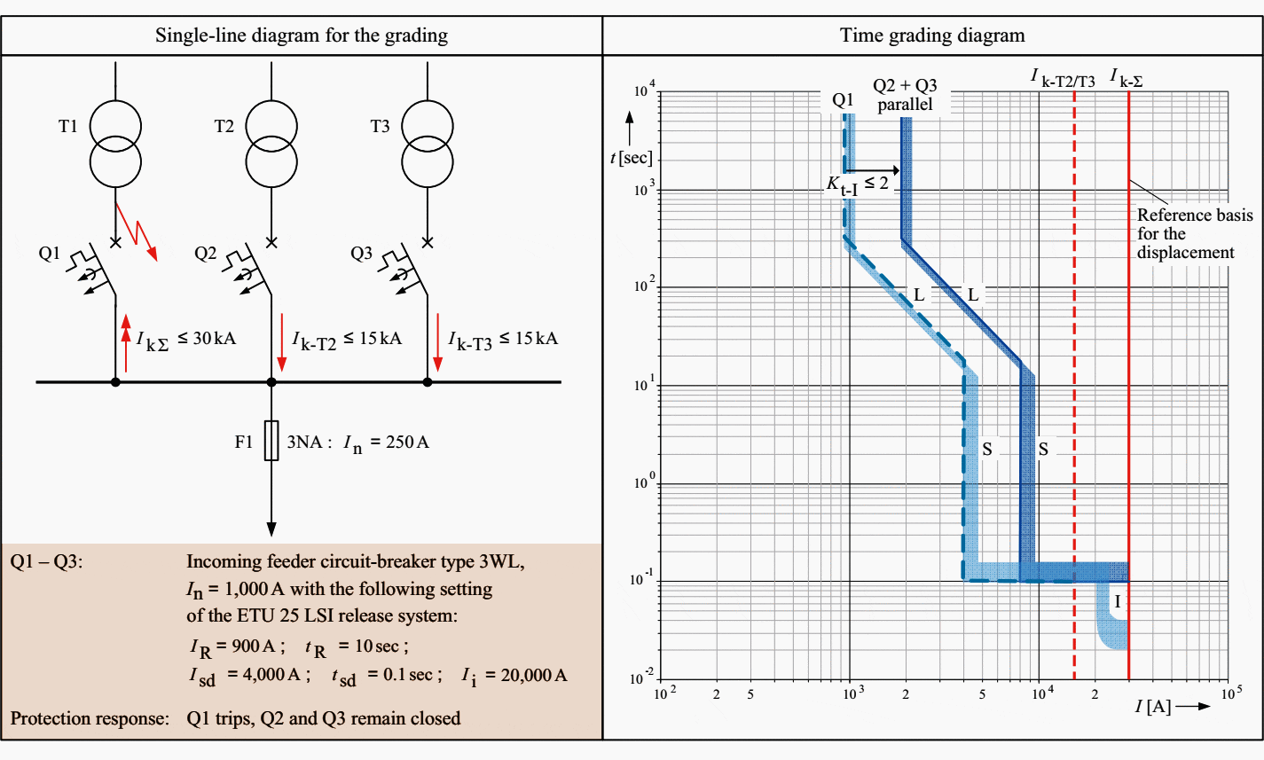

The selectivity example shown in Figure 2b is based on a perfectly symmetrical fault current distribution, that is, for the transformer circuit-breakers Q2 and Q3 in the faultless incoming feeders, a characteristic displacement factor of Kt-I = 30 kA/15 kA = 2 ideally applies.
In such a case, all incoming feeders would trip simultaneously and non-selectively.
To prevent non-selective tripping on strongly differing fault impedances, incoming feeder circuit-breakers must be used whose S releases (short-time-delay overcurrent releases) exhibit an I2t-dependent tripping characteristic.
The gain in selectivity that can be achieved using S releases with an I2t-dependent tripping characteristic is shown in Figure 2c.
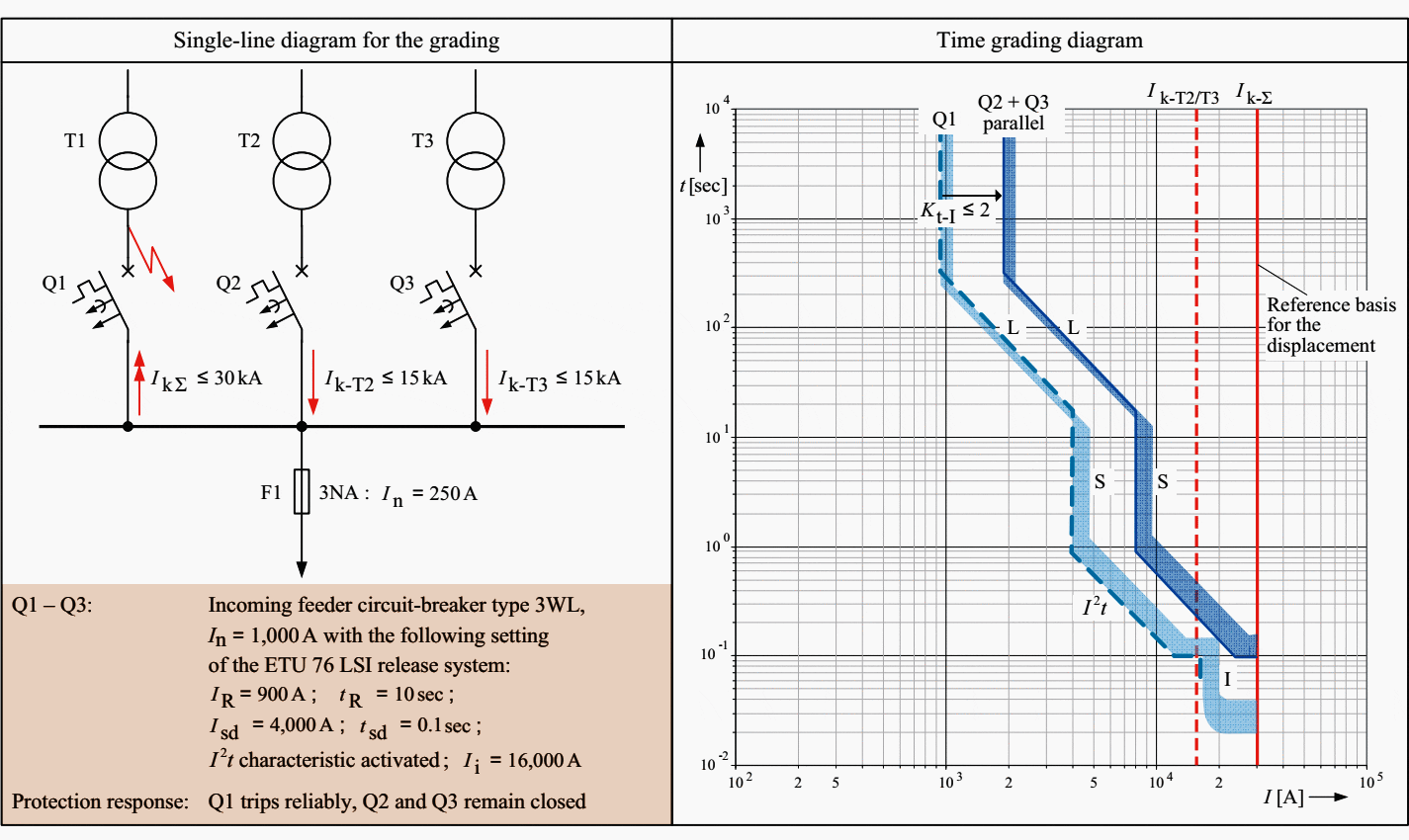

As a comparison of Figure 2c with Figure 2b shows, S releases with I2t-dependent tripping characteristics are notable for much enhanced current-time selectivity.
3. Incoming feeders connected in parallel through bus coupler circuit-breakers
Circuit-breakers with overcurrent releases are used as bus couplers to meet the following objectives:
- Fastest possible clearance of busbar faults,
- Fault restriction to the respective busbar section,
- Relieving the feeders of the effects of high total short-circuit currents.
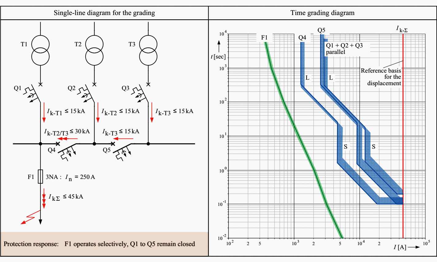
Figures 3a, 3b and 4 show the protection response of the transformer and bus coupler circuit-breakers in the case of three parallel incoming feeders and faults (fault on the outgoing feeder, fault on the incoming feeder) in the outer and central busbar section.
Short circuit on an outgoing feeder of the outer busbar section
Selectivity relations in the case of three identical transformers connected in parallel through bus coupler circuit-breakers (short circuit on an outgoing feeder)

Short circuit on an outgoing feeder of the central busbar section
Selectivity relations in the case of three identical transformers connected in parallel through bus coupler circuit-breakers (short circuit on an outgoing feeder)


Q1 – Q3 – Incoming feeder circuit-breaker type 3WL, In = 1,000 A with the following setting of the ETU 76 LSI release system:
- IR = 900 A
- tR = 10 sec
- Isd = 4,000 A
- tsd = 0.2 sec
- I2t characteristic activated
- Ii = 16,000 A
Q4, Q5 – Bus coupler circuit-breaker type 3WL, In = 1,000 A with the following setting of the ETU 76 LSI release system:
- IR = 800 A
- tR = 10 sec
- Isd = 3,000 A
- tsd = 0.1 sec
- I2t characteristic activated
- Ii = 32,000 A
Usually, further overcurrent protective devices are connected in series with the transformer and bus coupler circuit-breakers present in the multiple incoming supply of industrial LV networks.
Secondary-side terminal short circuit on the transformer of the outer busbar section
Selectivity relations in case of three identical transformers connected in parallel through bus coupler circuit-breakers (terminal short circuit on one transformer)


Secondary-side terminal short circuit on the transformer of the central busbar section
Selectivity relations in case of three identical transformers connected in parallel through bus coupler circuit-breakers (terminal short circuit on one transformer)


Q1 – Q3 – Incoming feeder circuit-breaker type 3WL, In = 1,000 A with the following setting of the ETU 76 LSI release system:
- IR = 900 A
- tR = 10 sec
- Isd = 4,000 A
- tsd = 0.2 sec
- I2t characteristic activated
- Ii = 16,000 A
Q4, Q5 – Bus coupler circuit-breaker type 3WL, In = 1,000 A with the following setting of the ETU 76 LSI release system:
- IR = 800 A
- tR = 10 sec
- Isd = 3,000 A
- tsd = 0.1 sec
- I2t characteristic activated
- Ii = 32,000 A
Because there are often economic reservations against the use of zone-selective interlocking (ZSI), the S releases of the transformer and bus coupler circuit-breakers are no longer time-graded instead.
In addition to setting identical time delays tsd, it is also usual to dispense with overcurrent releases in the busbar couplings altogether.
Sources: Planning Guide for Power Distribution Plants by Dr.-Ing. Hartmut Kiank and Dipl.-Ing. Wolfgang Fruth (Siemens)


Boa noite. Muito bom o material. Obrigado por compartilhar.
Information is suitable for Electrical Engineers/EIT and Technical Engineering, (CET, which we present to them to give a general understanding of power systems, associated power apparatus and protective measures/devices..