
Estimated Study Time: 5 minutes
Protective relay functions and data
This technical article will cover the gathering of information needed to calculate protective relay settings, the setting calculations for the various protective functions, typical generator/turbine withstand times for abnormal operating conditions, and the math associated with various types of impedance elements.
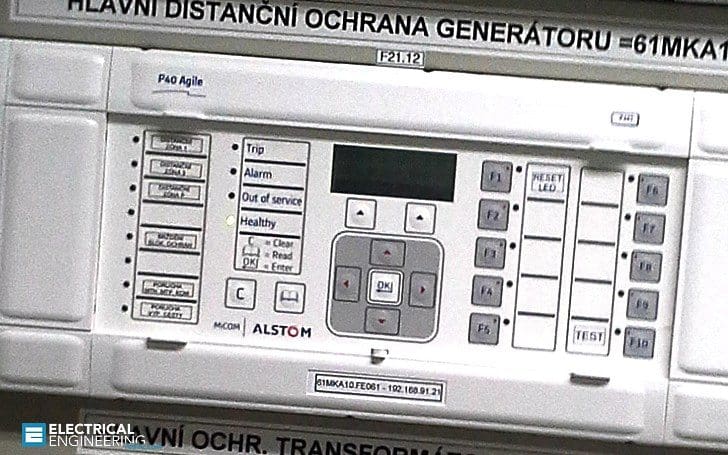 Setting the generator protective relay functions (photo credit: ase.cz)
Figures 1, 2, and 3 provide examples of organizing and massaging or converting the information to a more useful form for generators, step-up transformers, and their associated electrical systems. The information is for a 578.6 megavolt-amp (MVA), 24 kilovolt (kV) generator that is connected to the 765 kV bulk power transmission system.
Organizing the data in this manner will save significant time in developing and documenting the basis for the relay settings.
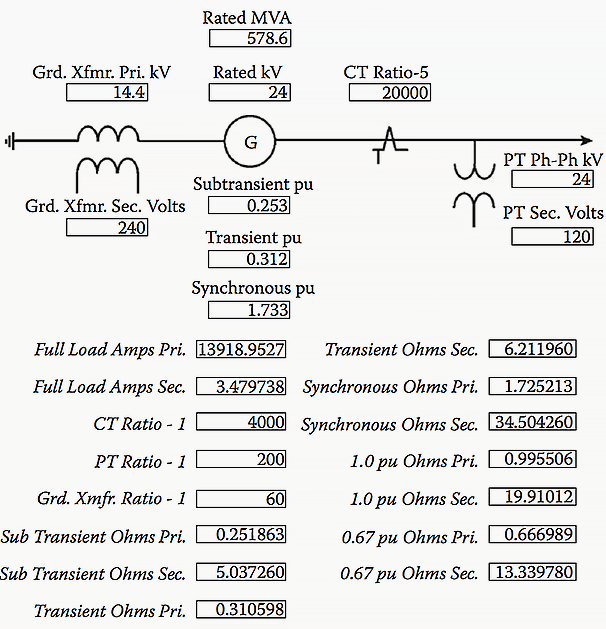
NOTES // The reactance values are direct axis saturated for the subtransient and transient ohms.
The top half of Figure 1 shows the generator data needed for the relay settings, including generator nameplate data, the direct axis saturated sub-transient, transient, and the synchronous per-unit reactances and the various primary and secondary instrument transformer ratings.
The bottom half of Figure 1 provides nominal currents, instrument transformer ratios, and various reactance ohms (not per unit) that will be used to develop the settings for the backup impedance, loss-of-excitation, and out-of-step relay functions.
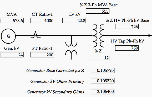
NOTES // Transformer impedance corrected to generated rated voltage and generator base MVA.
The transformer per-unit base impedance at 555 MVA needs to be converted to the generator base of 578.6 and corrected for voltage differences on the generator side of the transformer and tap differences on the high voltage side of the transformer. With the exception of secondary or relay ohms, the per-unit MVA conversions and corrections have already been discussed.
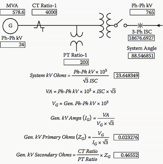
NOTES // The system 3-Ph ISC would not normally include the contribution from the generating unit under study.
Figure 3 above develops the high voltage switchyard secondary or relay ohms for the generator out-of-step function. Normally, this calculation would not include the short circuit contribution from the generator.
First, the system kV ohms and volt-amps (VA) are determined, then, the generator side amps and ohms are calculated, and finally, the secondary or relay ohms that represent the high voltage electrical system are developed. The system short circuit angle is not used in the calculation, but is needed for setting the out-of-step protective relay function.
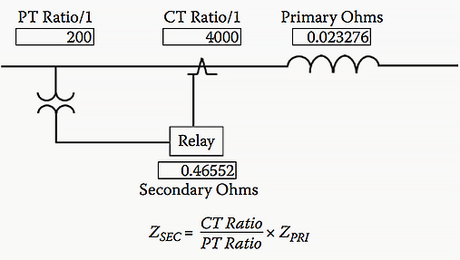
NOTES // ZSEC is the reflected primary ohms that the relay will measure.
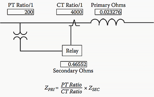
Figure 4 presents the expression for calculating secondary or relay ohms. The converse calculation in Figure 5 is used to convert relay ohms to primary side ohms.
Reference // Electrical Calculations and Guidelines for Generating Stations and Industrial Plants by Thomas E. Baker (Purchase hardcover from Amazon)
Related electrical guides & articles


Edvard Csanyi
Hi, I'm an electrical engineer, programmer and founder of EEP - Electrical Engineering Portal. I worked twelve years at Schneider Electric in the position of technical support for low- and medium-voltage projects and the design of busbar trunking systems.I'm highly specialized in the design of LV/MV switchgear and low-voltage, high-power busbar trunking (<6300A) in substations, commercial buildings and industry facilities. I'm also a professional in AutoCAD programming.
Profile: Edvard Csanyi

Dear Sir,
Could you please mentioned the actual reason of the following false tripping of two healthy feeders due to a single line to ground fault on the adjacent feeder.
Details are as follows: on
All three feeders are being fed from the same bus. Just adjacent to each other like feeder1,2 and 3. Feeder 3 had SLG fault and it caused feeders 1 and 2 also tripped on the same time.
Faulty Feeder 3 : Total length 35KM (Underground cable 3x50Sq.mm CU/XLPE/STA/PVC), CSH 120 (ZERO SEQUENCE CT) with SEPAM relay 1000+T42.
Over current setting 50/51: (Active Group A) ELEMENT1—STANDARD INVERSE TIME: 10A Delay 1S
ELEMENT2—STANDARD INVERSE TIME: 100A Delay 100mS
Earth fault setting 50N/51N : DEFINITE TIME 7A Delay 100Ms
One of its phase grounded due to excavation at 26km from plant.
Alarm recorded by SEPAM DIRECTIONAL EARTH FAULT
Healthy Feeder 2which also tripped : Total length 25KM (Underground cable 3x50Sq.mm CU/XLPE/STA/PVC), CSH 120 (ZERO SEQUENCE CT) with SEPAM relay 1000+T42.
Over current setting (Active Group A) ELEMENT1—-50/51: STANDARD INVERSE TIME: 10A Delay 1S
ELEMENT2——DEFINITE TIME 100A Delay 100Ms
Earth fault setting 50N/51N : DEFINITE TIME 7A Delay 100Ms
Alarm recorded by SEPAM EARTH FAULT
Healthy Feeder 1 which also tripped : Total length 20KM (Underground cable 3x50Sq.mm CU/XLPE/STA/PVC), CSH 120 (ZERO SEQUENCE CT) with SEPAM relay 1000+T40.
Over current setting (Active Group A) ELEMENT1—-50/51: DEFINITE TIME: 300A Delay 100mS
ELEMENT2——STANDARD INVERSE TIME 30A Delay 1S
Earth fault setting 50N/51N : DEFINITE TIME 7A Delay 100Ms
Alarm recorded by SEPAM EARTH FAULT
Alarm recorded by Incomer feeder for the bus BLOCKING TRANS.
Could you please explain the actual reason and measures to be taken to avoid such false tripping.
Best Regards.
dear mr. advard, let me introduce my self first, im sofyan, as a bachelor from one of university in Indonesian. I very happy and appreciated with this portal, because sometime we get some problem about thinking hows it work, hows that work, why like that… but your sharing in this portal really simple to make me know about our questions,. thank about that.
I have a suggestion for better about this portal than this time, can you do addition about some real example in rows of calculations, its really help us as a begginers.
thank you my dear.