
Estimated Study Time: 19 minutes
Substation’s visual impact
The aesthetics of the substation should be of greatest significance to the community. To ensure environmental compatibility and community acceptance, it is vital to involve the community in the early stages of a project.
 Seven steps to improve visual impact of a power substation
It is possible that environmental impact assessments were not conducted during the initial installation of several of the current substations, which date back tens of years. Moreover, due to population increase and urban sprawl, many substations that were initially situated outside of population centers to minimize their visual impact are now encircled by highly populated residential and commercial areas.
In this technical article, we’ll take a look at existing power substations, figure out what might be making them look ugly, and then offer some solutions to make them look better.
To conduct a thorough study of the necessary work, it is necessary to consider each component of the substation individually.
- Precautions to be taken with the substation equipment and layout
- Precautions regarding substation buildings and warehouses
- Measures to be taken on perimeter fences
- Important steps regarding access roads and gates
- Measures to be taken on gravel surfaces
- What has to be done regarding lighting
- Awkward slopes and what can be done
- Attachment (PDF) 🔗 Download ‘Electrical Power Systems for the Undergraduate Students in Electrical Engineering’
1. Precautions to be taken with the substation equipment and layout
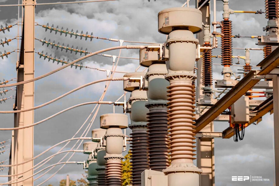
The arrangement of equipment in a substation, particularly in air-insulated substations, significantly influences the substation’s aesthetics. Transmission line gantries for incoming and outgoing lines frequently generate the greatest adverse visual impact.
The height of these gantries is dependent upon the voltage level of the substation; a standard 400 kV substation gantry typically measures 25-30 meters in height.
Common strategies to mitigate the visual impact of substation equipment encompass:
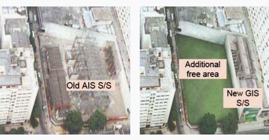
Strategy #1: Replace AIS with GIS
The first strategy is transforming an extension of a current substation (or the outside substation itself) into a gas-insulated substation (GIS). This method is prohibitively expensive and may not be viable.
Figure 1 – Comparing GIS and AIS substation space
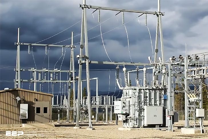
Strategy #2: Low-profile equipment
The second strategy, as an option is a low-profile equipment configuration utilizing rigid tubular conductors mounted on post insulators instead of traditional flexible strung conductors, along with redesigned gantry and equipment structures to replace steel lattice frameworks.
A rigid conductor arrangement possesses superior aesthetic appeal compared to flexible strung conductors.
Figure 2 – Substation rigid busbars
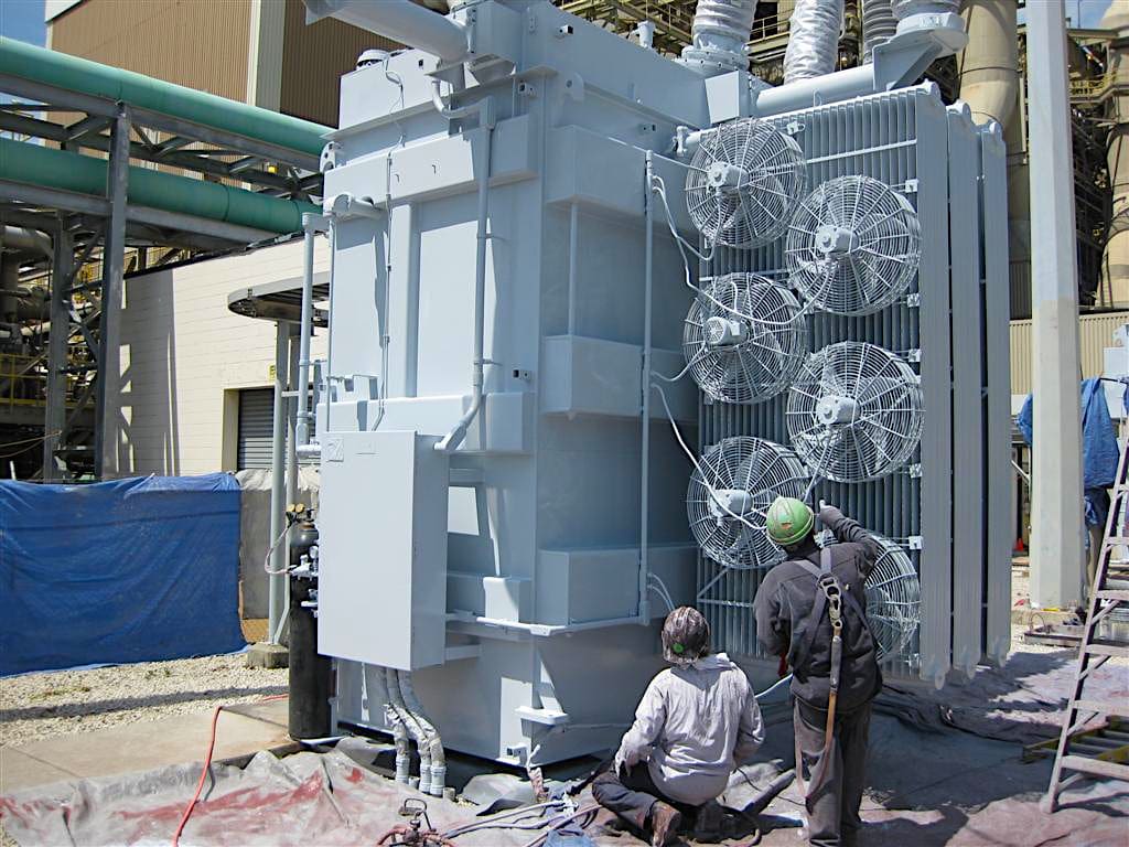
Strategy #3: Coating heavy equipment
Third strategy is coating heavy equipment, including transformers and their supporting frameworks, so they blend with the surrounding area.
Figure 3 – Transformer coating
2. Precautions Regarding Buildings and Warehouses
While it is easy to consider the visual impact of buildings and storage areas when designing and implementing a new substation, it may be quite a challenge for older substations to do the same.
2.1 Substation Building
Control buildings, relay shelters, and enclosures for switchgear are some of the building types that can be found within a substation. At least one control building is present in the majority of substations.
Some older substations may have multiple ancillary structures, such as:
- The residences of the former operational and maintenance personnel, which number three or four.
- Buildings designed to hold pumping equipment and water tanks—also known as pump houses.
- A workshop for performing repairs and maintenance on-site.
See Figure 4.
Figure 4 -The roof of the control building is painted blue to pair with support structures for transformer incoming/outgoing lines
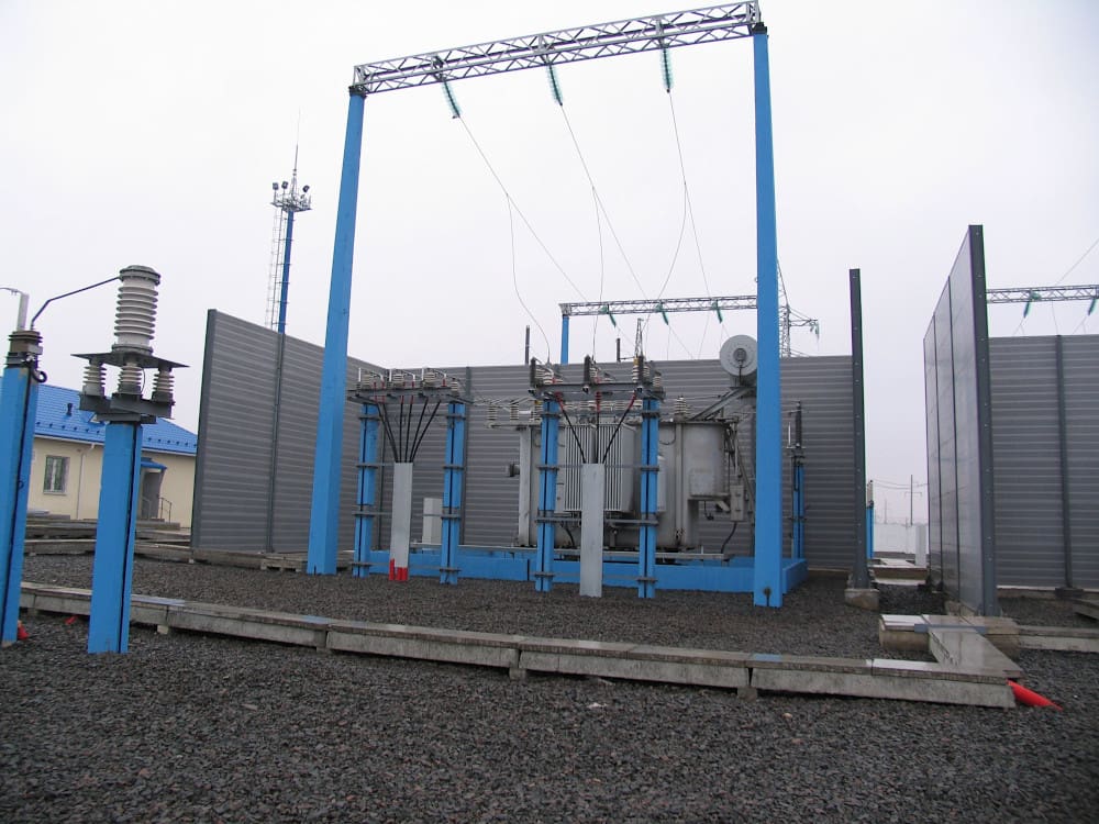
Blending a substation into its environment during design is significantly easier than doing it after construction, as previously mentioned. Some steps can be taken to achieve this, though, such as painting the building’s façade a color that blends in with its natural environment.
Figure 5 – This relay shelter has been designed to reflect local architectural styles
2.2 Warehouses and storage areas
Substations may also include clearly defined facilities for storing spare parts and waste materials. Some substations may have waste products and spare parts dispersed across the site, making it impossible for an outsider to differentiate between the two.
Figure 6 – Substation in construction lacking storage area
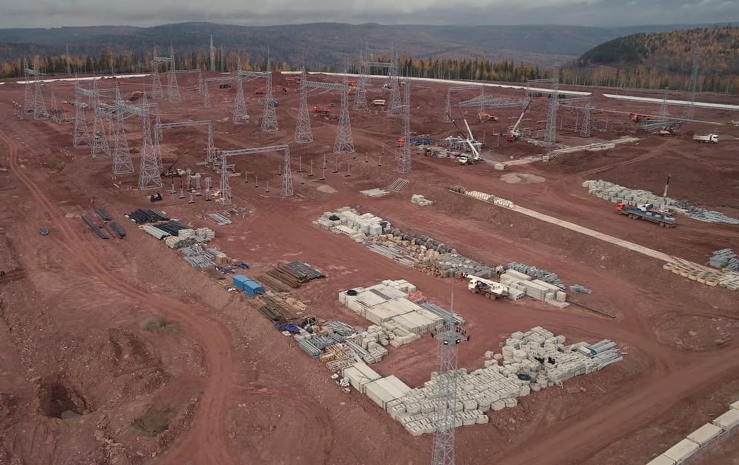
A preferable alternative would be to designate separate storage locations for spare parts and waste goods. These places should be properly identified and, if possible, should not be positioned in regions of high visibility.
Routine maintenance of storage and trash sites is advised in order to improve substation aesthetics and achieve community acceptability.
Figure 7 – The area for waste materials is clearly not demarcated by a chain-link fence or a sign

3. Measures to be taken on Perimeter Fences
Power regulations and guidelines mandate that all power substations be secured by a chain-link fence or masonry wall of certain height. The perimeter fence must display high voltage warning signs on all sides to caution non-substation personnel against trespassing on the site.
Substations are required to be enclosed by one or more fences around the whole perimeter of the facility. Typically, perimeter fence consists of reinforced galvanized steel chain links. Alternatively, substations may be surrounded by concrete barriers.
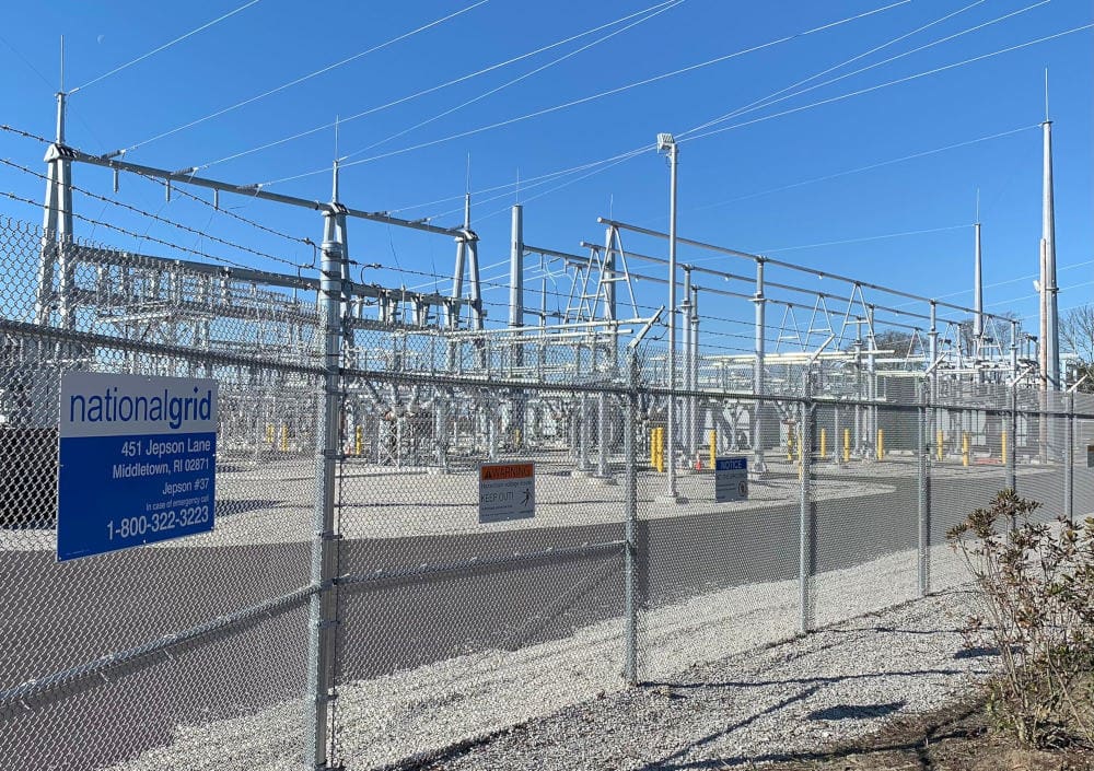
Moreover, the implementation of a chain-link fence may motivate substation personnel to maintain the interior in an orderly manner, as its contents will be accessible to the public.
Figure 8 – The interior of the substation is visible through the chain-link fence
To visually screen the substation with natural features in the environment, plants can be installed along the perimeter of the chain-link fence to create a fence of vegetation. This way we can diminish the visual impact of the substation by alterations to the perimeter fence.
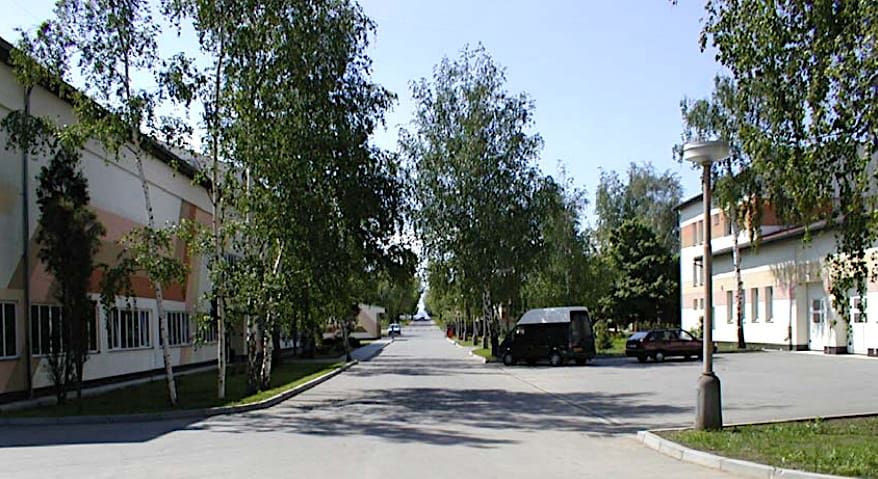
In the case of a 400/220kV transmission substation in the Figure below, the interior of the substation is lined with trees.
Figure 9 – The chain-link fence is hardly noticeable
4. Important Steps Regarding Access Roads and Gates
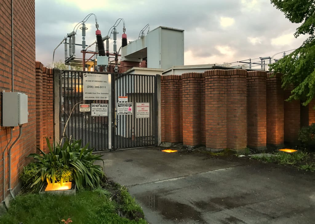
Substations typically have metal gates installed for vehicle access. Usually, a single-leaf gate is utilized to grant access to personnel. The chances of being able to change the gate’s design after installation are low.
Hence, it’s probable that current gates will only be able to have their paint colors changed if any changes are made to their design.
Figure 10 – Substation gates
5. Measures to be taken on Gravel Surfaces
Substation ground covering must meet certain standards set out by power regulations. Dust and other particles from the substation site must not be allowed to spread, hence specific steps must be implemented to achieve this. Gravel, grass, and asphalt paving are the three most typical ground cover types found within substations.
In air-insulated switchyards, gravel is a typical ground covering. If you want the substation to blend in with the landscape, you’ll need to be careful with the asphalt or gravel color you choose. See Figure 11.
It might be more appropriate to use dark gravel, which mimics the surrounding environment’s color palette, to conceal the substation.
Figure 11 – Poor choice of gravel colour has made the visual impact of this substation much greater

It is also not a good idea to use glass or mica since they can cause glare on bright days, which draws even more attention to the substation and can be a pain for the people working there. Ochre-colored gravel, with its natural tone that can fit in with natural environments, could be a good solution in some situations.
You should be careful not to select colors for the substation surface covering that could be too contrasty with the natural setting. The absence of organic matter and the varied oxidation rates of terrigenous materials cause deeper soil layers to typically have a lighter color than the surface of the land.
Regular maintenance is also necessary for gravel in order to control plant development. A hallmark of substation maintenance until recently was the regular application of herbicides to prevent plant growth within the substation. Because grid operators are under pressure to reduce pesticide use to prevent the contamination of soil and natural water supplies, this has become a concern in many nations.
An interesting substitute is the “dry-meadow” idea, which calls for a combination of dirt and broken rock. The presence of ballast in the soil controls the growth of the grass, therefore this system requires minimum upkeep.
Further Study – Technical Documentation for a Turnkey Substation
Further Study – Execution of a Turnkey Substation Project: How not to step on the same rake again
Execution of a Turnkey Substation Project: How not to step on the same rake again
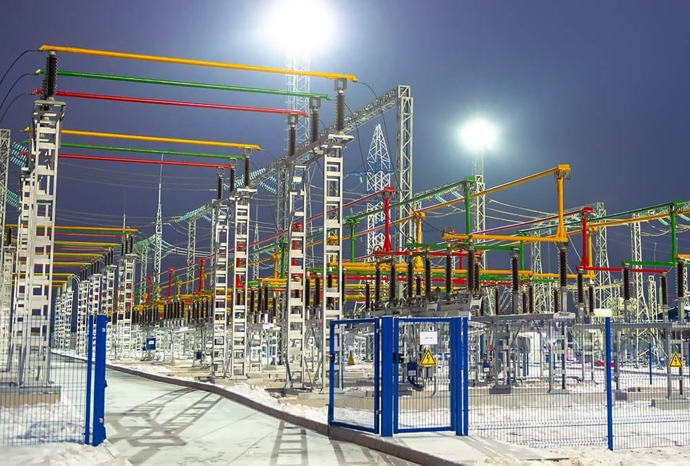
6. What has to be done regarding lighting
In order to facilitate nighttime emergency work and to prevent break-ins and theft, substations should be fitted with powerful lighting systems. Substations sometimes have powerful illumination that can be a nuisance to local residents due to the increased light pollution in the area. The local wildlife’s habits could be influenced by the illumination as well.
To circumvent these consequences, it is recommended to establish a lighting control system that limits the lumens in the switchyard. At night, it is also possible to apply specialized lighting effects like spot lighting, light guides, color lights, etc.
It is advised that the substation lighting system be comprised of two parts: one that deters burglars with a lower light intensity and another that improves the yard’s visibility for substation visits and nighttime repairs. In the control room, there can be a physical switch for the backup system.
In order to floodlight the substation in case of unwanted access, an automated lighting system that is linked to the substation control system could also be considered.
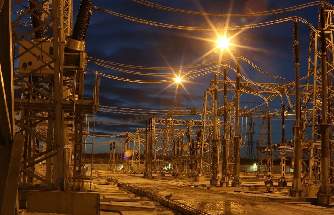
In order to determine the best lighting system for a substation in terms of efficiency, effectiveness, cost, and user-friendliness, it is typically advised to undertake a lighting study.
Figure 12 – An example of good lighting design in a substation
7. Awkward slopes and what can be done
Substations are rarely located on precisely level ground and can take up to ten hectares of space. No gradient should be more than 5%. Partitioning the land into many flat aprons and connecting their levels with slopes or embankments is sometimes required to accomplish this. Site grading is sometimes not feasible or cost-effective in mountainous areas, hence this is the usual practice.
The gradual wear and tear caused by erosion will eventually affect these slopes, be they cuttings or embankments. The gradient, the weather, and the land’s characteristics will determine the amount of erosion.
In order to prevent erosion, maintenance work is not recommended on slopes.
A substation with a “stepped” switchyard that takes advantage of the surrounding landscape’s natural slopes is shown in case study below. Here, the cost of land leveling the substation was significantly lowered by implementing a stepped switchyard.
Figure 13 – 275/154/77kV stepped substation constructed on a mountain
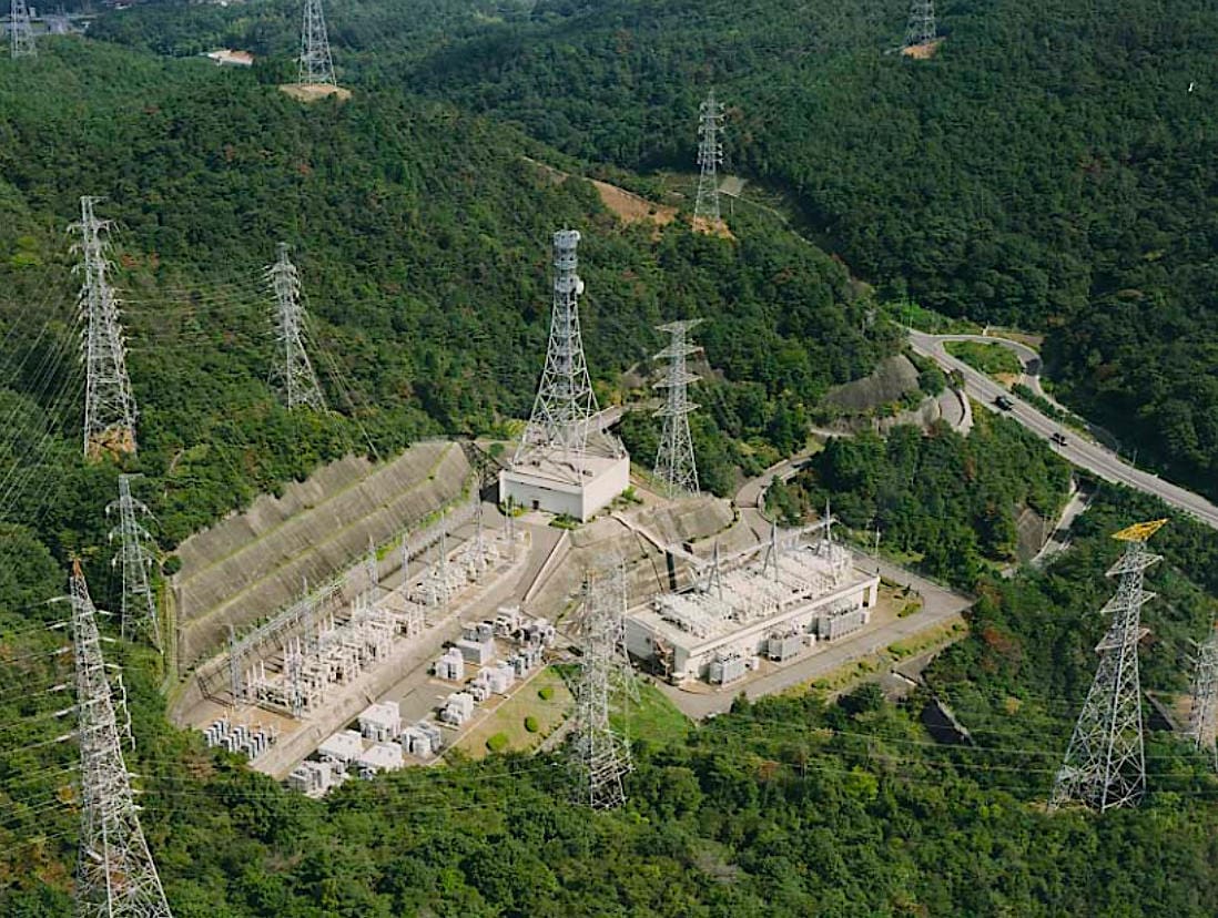
This case study pertains to a 275/154/77kV substation constructed on a mountain. Two critical factors must be considered when situating a substation on a mountain: obtaining a level location of sufficient size and assessing the substation’s impact on the surrounding terrain. Both problems can be resolved via a “stepped” switchyard.
The steps of the substation were built as follows:
- 1st Layer: 275kV switchgear and 275/ 154kV transformer yard
- 2nd Layer: 154/77kV transformer and 77kV shunt reactor
- 3rd Layer: 154 kV switchyard
- 4th Layer: Control/ protection room and 77kV switchyard
Minimal impact on the natural environment and drastic curtailment of land reclamation expenditure were achieved.
Watch Video – Electrical Substation Slope Erosion Protection
8. Attachment (PDF): Electrical Power Systems for the Undergraduate Students in Electrical Engineering
Download: Electrical Power Systems for the Undergraduate Students in Electrical Engineering (for premium members only):
Reference: Working Group B3.03
Related electrical guides & articles


Edvard Csanyi
Hi, I'm an electrical engineer, programmer and founder of EEP - Electrical Engineering Portal. I worked twelve years at Schneider Electric in the position of technical support for low- and medium-voltage projects and the design of busbar trunking systems.I'm highly specialized in the design of LV/MV switchgear and low-voltage, high-power busbar trunking (<6300A) in substations, commercial buildings and industry facilities. I'm also a professional in AutoCAD programming.
Profile: Edvard Csanyi
