


Estimated Study Time: 54 minutes
EPLAN Schematics and Drawings
This comprehensive technical article provides an exhaustive, granular analysis of the EPLAN schematics and structural drawings for the 10kV Motor Control Centre (MCC), originally documented by EPLAN Software. The medium voltage switchgear assembly is designed to provide robust control, metering, and protection for high-voltage industrial motor applications and feeder lines.
 Sheet-By-Sheet Analysis of 10kV Motor Control Centre (MCC) Technical Drawings in EPLAN
This technical article systematically breaks down the entire document array, navigating from the high-level structural dimensions and physical layout of the switchgear panels down to the intricate relay logic, interlocks, and terminal point mappings.
The 10kV Motor Control Centre is structured to conform to IEC standards, specifically adhering to guidelines regarding metal-enclosed switchgear operation, internal arc classification, and control circuit reliability.
The provided drawing set encompasses 71 sheets (as noted on the title page and table of contents, sheets 2 to 2.b), covering everything from the single-line primary distribution diagrams to the highly complex binary input mappings of the protection relays.
The analysis will guide the reader through each drawing sheet, claryfying the purpose of the components, their exact row and column locations on the schematics, and the functional philosophy governing their operation.
The schematics illustrate this demarcation. Special attention in this report is heavily weighted toward the critical safety and operational systems requested: the equipment descriptions, the tripping circuits that isolate faults, the interlocking mechanisms that prevent catastrophic operator errors, and the blocking and alarm signals that provide system awareness and coordination.
By learning these elements, this article serves as a definitive guide to the operational mechanics of the documented 10kV MCC.
Here is the download link for the complete PDF document with drawings (68 pages). Open it up, so you can follow the discussion.
Schematics (PDF, 0.8 MB)
- Switchgear Layout and Foundation Details
- Primary & Secondary Equipment Description
- Auxiliary Voltage Circuits and Control Circuits
- Analysis of Tripping and Closing Circuits
- Tripping Interlocking and Safety Mechanisms
- Blocking and Alarm Signals
- Terminal Interconnections and Signal Routing
- Binary Input Mapping and Protection Relay Logic
- Findings, Inconsistencies and Points to Verify
- Conclusion and Switchgear Summary
- Deep Technical Component Analysis:
- Attachment (PDF) 🔗 DC Grid Protection Guide: Fault Analysis and System Design
1. Switchgear Layout and Foundation Details
The physical configuration of the 10kV Motor Control Centre is explicitly detailed in the ‘Front View (total)’ drawings on sheets =S01&ELU/1 and =S01&ELU/2. The switchgear lineup is constructed as a contiguous array of modular, metal-enclosed cubicles.
The total height of the assembly is defined as 2200 mm, a standard dimension that accommodates the vertical stacking of the circuit breaker truck compartment, the busbar compartment, and the low-voltage control cabinet situated at the top of each panel.
The lineup consists of several distinct panels, each dedicated to a specific operational role within the substation environment. Moving across the front view, the widths of the panels vary based on their internal equipment requirements.
We observe panels with widths of 800 mm, 640 mm, and 650 mm.
Figure 1 – MCC Front View
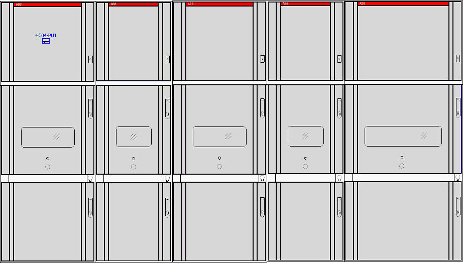
The wider 800 mm panels typically house the incoming feeders or complex motor starters that require additional spatial volume for current transformers, heavy cabling, and potential autotransformer accommodations. The 650 mm and 640 mm panels are standard widths for outgoing motor feeders and metering panels.
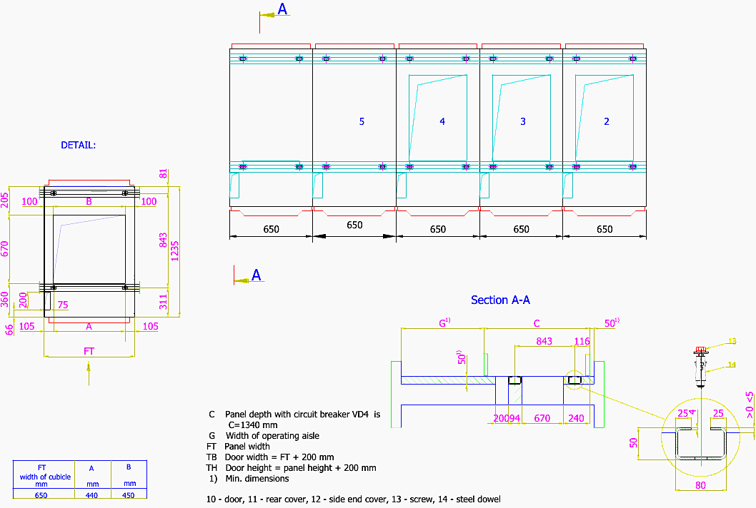
Sheet =S01&ELU/3 provides the ‘Foundation frame‘ details, which dictate the civil engineering requirements for the switchgear installation. The depth of the panels equipped with the primary VD4 circuit breakers is specified as 1340 mm.
Furthermore, the drawing explicitly mandates a minimum operating aisle width (labeled as dimension ‘G‘) to ensure safe personnel movement and breaker extraction.
The panel width (‘FT’) directly influences the required floor cutout dimensions. The foundation drawing illustrates the exact placement for the 10-door, 11-rear cover, and 12-side end cover structural mounting points, ensuring the mechanical integrity of the metal-clad structure during an internal arc fault event.
Figure 2 – MCC Foundation frames
2. Primary & Secondary Equipment Description
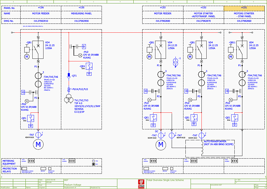
The primary electrical components are mapped on the ‘Total Overview Single Line Scheme’ on sheet =S01&EFA/4. This drawing provides the macro-level view of the power distribution architecture. The panels are designated as follows:
- +C06 (Motor Feeder),
- +C05 (Measuring Panel),
- +C04 (Motor Feeder),
- +C03 (Incoming Feeder),
- +C02 (Motor Starter / Autotransformer Panel), and
- +C01 (Motor Starter Star Panel).
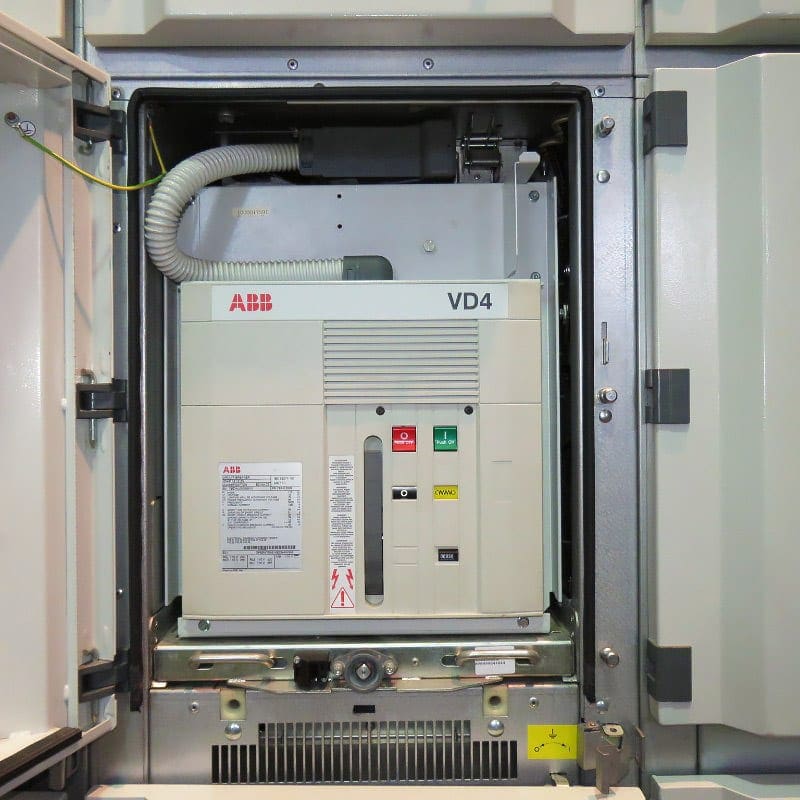
At the heart of the power interruption capability in panels +C01, +C03, +C04, and +C06 is the ABB VD4 vacuum circuit breaker. The specific model referenced in the drawings is the VD4 24.12.25 1250A. This indicates a breaker rated for up to 24kV maximum system voltage, a short-circuit breaking current of 25kA, and a nominal continuous current rating of 1250A.
The VD4 utilizes vacuum interrupters embedded in epoxy resin poles.
Figure 3 – MCC Single Line Scheme
When a trip command is issued, the spring-operated mechanism rapidly separates the contacts within the vacuum chamber. The high dielectric strength of the vacuum instantly quenches the resulting arc at the first zero-crossing of the AC current waveform, ensuring rapid and safe fault clearance.
This breaker is truck-mounted, allowing it to be racked in (Service position) and out (Test/Disconnected position), which is a critical feature integrated into the interlocking logic.
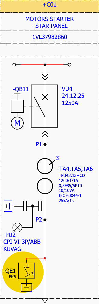
The operation of the EK6 is tightly interlocked with the VD4 breaker truck position.
Figure 4 – EK6 Earthing Switch in +C01 panel
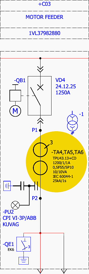
Current and voltage measurement is handled by high-precision instrument transformers. The Current Transformers (CTs) are specified as TPU43.13+CD. These are high-performance cast-resin CTs with a ratio of 1200/1/1A, meaning they have a primary rating of 1200A and two secondary cores rated at 1A each.
The 5P10 designation guarantees that the CT will maintain its specified accuracy up to 10 times the rated current without core saturation, which is vital for the overcurrent protection relays to ‘see’ the true magnitude of a fault.
Figure 5 – Current Transformers (CTs) in +C03 Motor Feeder Panel
The Voltage Transformers (VTs), designated as TJP 4.0, provide stepping down of the 10kV primary voltage to standard secondary voltages (e.g., 100V or 110V) for the metering equipment and directional protection elements.
The secondary protection is provided by an array of digital relays. The primary motor protection relay utilized in the starter panels is the ABB REM5438M (motor protection terminal listed on the overview sheet). This device handles comprehensive motor protection algorithms, including thermal overload, locked rotor, repeated starts, unbalance, and short circuit protection.
It interfaces with an RTD card to directly monitor motor winding and bearing temperatures.
Figure 6 – Arc Fault Protection Using the VAMP 255 and REA 101 relays
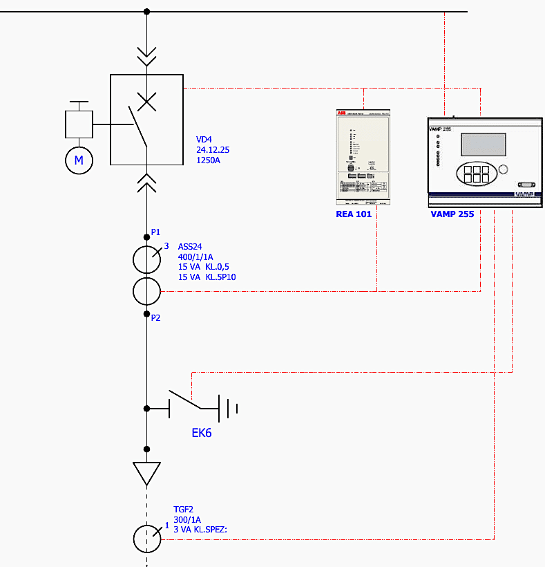
Additionally, the system incorporates dedicated arc fault protection using the VAMP 255 and REA 101 relays. These systems use optical sensors distributed throughout the busbar and cable compartments. If an internal arc flash occurs, the optical sensors detect the intense light, and the relay simultaneously measures an overcurrent spike.
This dual-verification allows the VAMP/REA system to issue a trip command in less than 2 milliseconds, vastly reducing the destructive energy of an internal arc.
Table 1 – Primary Equipment Tags
| Tag | Type as drawn | Function |
| -QB1 / -QB11 | VD4 24.12.25, 1250 A | Withdrawable vacuum circuit breaker, 24 kV class, motor-charged spring mechanism |
| -QE1 / -QE4 | EK6 | Earthing switch with making capacity, panel-mounted |
| -TA4, -TA5, -TA6 | TPU43.13+CD, 1200/1/1 A, 0,5FS5/5P10, 10/10 VA | Two-core phase CTs: metering core (0,5FS5) and protection core (5P10) |
| -TA4/5/6 (+C01 detail) | ASS24, 400/1/1 A, 15 VA Kl. 0,5 / 15 VA Kl. 5P10 | Phase CTs shown on the +C01 single line sheet 21 |
| -TA7 / -TA9 | KDKM 06J2 and TGF2, 300/1 A, 3 VA Kl. SPEZ. | Core-balance CT for sensitive earth-fault current I0 |
| TV1, TV2, TV3 | TJP 4.0, 10/V3//0,1/V3//0,1/3, 50/50 VA, Cl. 0,5/3P | Busbar voltage transformers with open-delta residual winding |
| -PU2 | CPI VI-3P / ABB KUVAG | Three-phase capacitive voltage-presence indicator |
| -BR1 | VAMP 255 | Main numerical motor protection relay |
| -F18 | REA 101 (ABB) | Arc protection relay with optical sensor channels |
| REM543BM 213AAAA | ABB REM 543 with RTD card | Motor protection terminal listed on the overview sheet |
| SPA-ZC302 | Profibus gateway | Station communication interface |
| -MP | Rittal TS 8808.500, 800/2000/800 | Low-voltage compartment mounting panel |
3. Auxiliary Voltage Circuits and Control Circuits
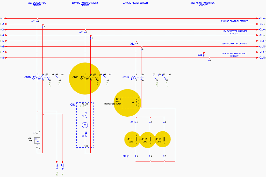
The operational reliability of the MCC depends entirely on the integrity of its auxiliary power supplies. The detailed schematic for these supplies is located on sheet =S01+C01&EFS/5 (Aux. voltage supply). The drawing is divided vertically into discrete functional circuits, typically referenced by columns (e.g., columns 1 through 8 across the page).
The primary control voltage is 110V DC, entering the panel through terminal block -XI1. The 110V DC Control Circuit is protected by a two-pole miniature circuit breaker (MCB) designated as -FB10.
This MCB, explicitly listed in the bill of materials as a Siemens 55X2106-8 (though standard Siemens part numbers usually follow the 5SY4 or 5SP format, the drawing specifically uses this string), ensures that a short circuit in the delicate relay logic wiring does not compromise the entire substation DC battery bank.
Figure 7 – Interconnection Terminal -X11 that distributes 110V DC Control Circuit
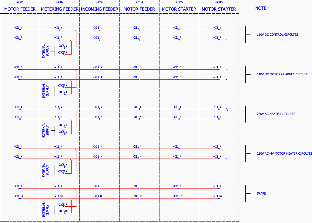
Parallel to this is the 110V DC Motor Charger Circuit, protected by -FB11. This circuit is exclusively dedicated to supplying power to the charging motor -MS inside the VD4 circuit breaker.
Isolating the spring charging motor from the sensitive control logic prevents the heavy inductive current draw of the motor from causing voltage dips or transients that could reset the digital protection relays.
The operation of these heaters is regulated by a thermostatic switch -BH1, which has an adjustable range of 0-60°C. When the internal ambient temperature drops below the setpoint (or humidity rises, depending on the specific hygrostat/thermostat combo), -BH1 closes its contact, energizing the 20W heaters to raise the temperature above the dew point.
An additional 230V AC circuit is provided specifically for the MV Motor Space Heater, routed through terminal -XI1 pins 7 and 8, ensuring the primary 10kV motors remain dry during prolonged standstill periods.
Figure 8 – Auxiliary Voltage Supply
4. Analysis of Tripping and Closing Circuits
The core function of the switchgear is its ability to reliably close and open the primary circuit under both normal and fault conditions. The Closing Circuit is depicted on sheet =S01+C01&EFS/12, and the Tripping Circuit on sheet =S01+C01&EFS/13. These schematics require careful column-by-column analysis to understand the logical flow of command signals.
Starting with the Closing Circuit =S01+C01&EFS/12, the 110V DC positive rail -a101 feeds into the circuit. The actual closing operation of the VD4 breaker is initiated by energizing the shunt closing release coil, designated as -Y3.
Once past the block, the command is routed through the local/remote control switches and the internal auxiliary contacts of the breaker itself (-S1, -S2, -S3).
Figure 9 – Closing Circuits
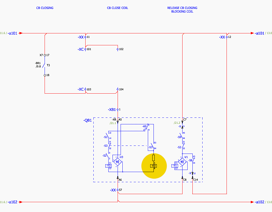
Specifically, the breaker’s internal anti-pumping relay -K0 is integrated here. If a continuous closing signal is applied while a trip condition exists, the breaker will open and the -K0 relay will latch, preventing the breaker from repeatedly closing and opening (pumping) and destroying itself.
The Tripping Circuit =S01+C01&EFS/13 is intentionally designed for maximum redundancy and failsafe operation. The primary shunt tripping coil is identified as -Y2. Unlike the closing circuit, which has many permissive constraints in series, the tripping circuit utilizes multiple parallel pathways to ensure that any critical protection function can immediately dump 110V DC into the -Y2 coil.
As seen on the schematic, the trip signal from the main REM5438M protection relay enters the circuit.
Parallel to this are specialized, high-speed trip routes. For instance, the ‘ARC TRIP’ signal (originating from the REA 101 / VAMP 255 arc protection system) has a direct, hardwired path to the trip coil, bypassing all non-essential logic to guarantee the absolute minimum clearing time.
Figure 10 – Tripping Circuits
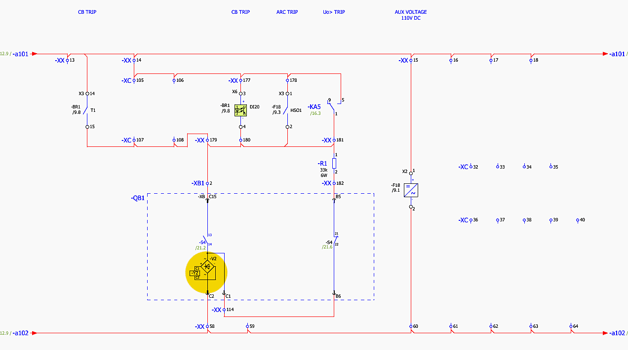
Similarly, the ‘Uo TRIP’ (zero-sequence voltage trip for ungrounded or impedance-grounded earth faults) commands immediate opening.
Furthermore, the tripping circuit features continuous coil supervision. A small trickle current passes through the Y2 trip coil via a supervision relay or the digital input of the REM5438M. If the internal wire of the trip coil breaks, or if the 110V DC tripping voltage is lost, this trickle current is interrupted.
The system instantly recognizes this as a critical failure and raises a ‘Trip Circuit Supervision‘ alarm, alerting operators that the breaker is functionally paralyzed.
5. Tripping Interlocking and Safety Mechanisms
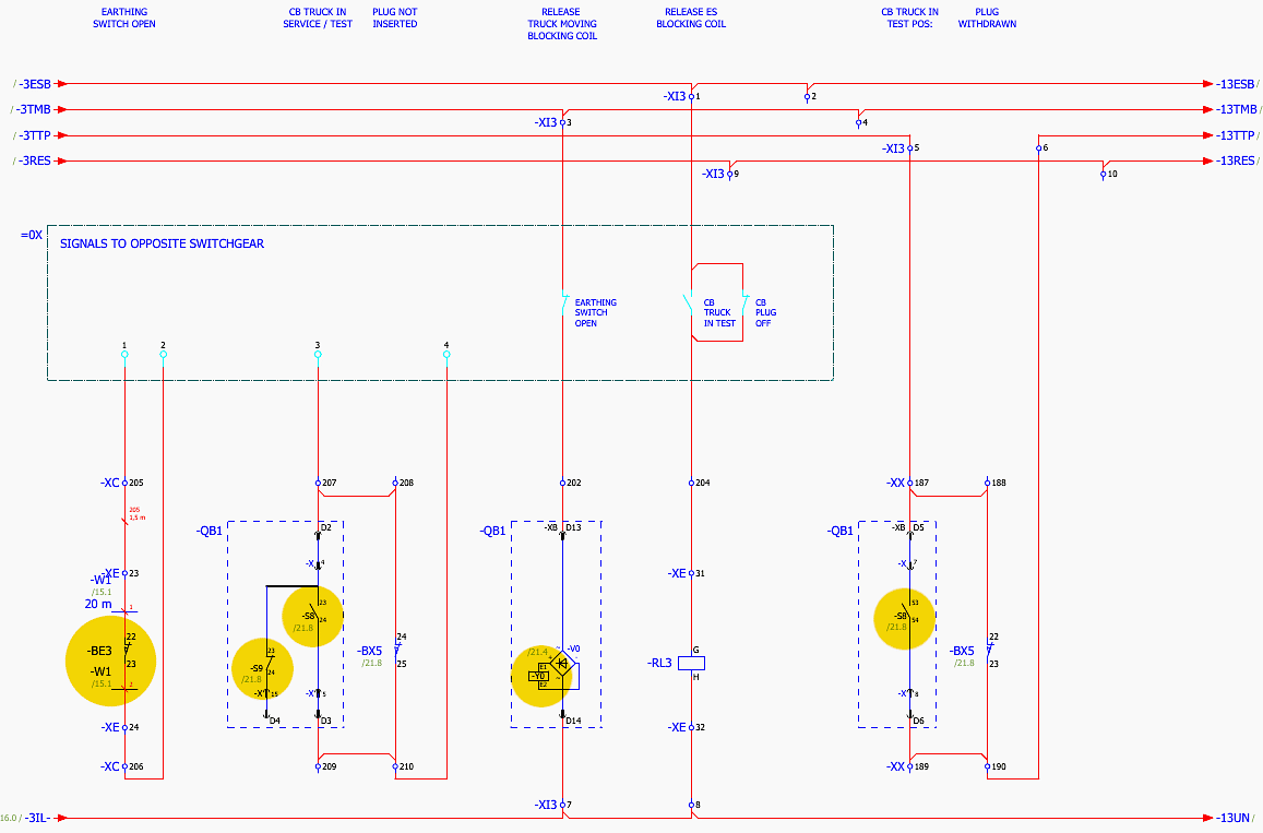
Interlocking is the cornerstone of switchgear safety, designed to physically and electrically prevent operators from performing sequences that would result in fatal arc flashes or equipment destruction. The interlocking logic for the 10kV MCC is extensively detailed on sheets =S01+C01&EFS/14 and =S01+C01&EFS/15.
The most critical mechanical and electrical interlock exists between the VD4 Circuit Breaker truck position and the EK6 Earthing Switch -QE1.
On the schematic =S01+C01&EFS/14, this is governed by the ‘CB Truck in Test Pos’ contacts. The earthing switch mechanism contains an electrical blocking coil -Y0. If the VD4 breaker is in the ‘Service’ position, the 110V DC supply to the earthing switch blocking coil is interrupted by the breaker’s position auxiliary contacts (-S8, -S9).
The blocking coil remains de-energized, keeping a physical locking pin engaged in the earthing switch drive mechanism, making it physically impossible for an operator to insert the operating handle and close the earth switch onto live busbars.
Figure 11 – Interlocking Circuits
Conversely, the Circuit Breaker cannot be racked from the ‘Test’ position into the ‘Service’ position if the Earthing Switch is closed.
The drawing shows the ‘Earthing Switch Open’ signal routing through auxiliary contacts (-BE2, -BE3) located on the EK6 switch shaft. Only when the earthing switch is fully open do these contacts close, completing the circuit to energize the ‘Release Truck Moving Blocking Coil’ (often a locking magnet on the breaker truck chassis).
If the earthing switch is closed, the magnet remains locked, preventing the lead screw from turning and blocking the breaker from being racked into the live busbars and creating a dead short to ground.
Additional interlocking involves the secondary control plug. The ‘Plug Not Inserted’ logic ensures that the breaker cannot be operated electrically if the multi-pin control umbilical is disconnected.
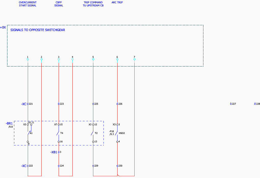
Auxiliary contacts (like -BX5) monitor the physical insertion of this plug. Furthermore, ‘Signals to Opposite Switchgear’ denote cross-panel interlocking, ensuring that in complex transfer schemes (like a main-tie-main arrangement), breakers coordinate their states to prevent out-of-phase paralleling or connecting disparate sources.
Figure 12 – Interlocking Circuits
6. Blocking and Alarm Signals
Situational awareness and protection coordination are managed by a complex array of blocking and alarm signals, meticulously mapped on sheets =S01+C01&EFS/16 (Blocking Signals) and =S01+C01&EFS/17 (Alarm Signals).
Blocking signals (=S01+C01&EFS/16) are fast-acting logic commands used to enforce protection selectivity. A prime example shown in the drawings is the ‘Overcurrent Blocking Signal’.
This signal temporarily freezes the upstream relay’s fast overcurrent element, allowing the localized feeder breaker to clear the fault.
Figure 13 – Blocking Signals
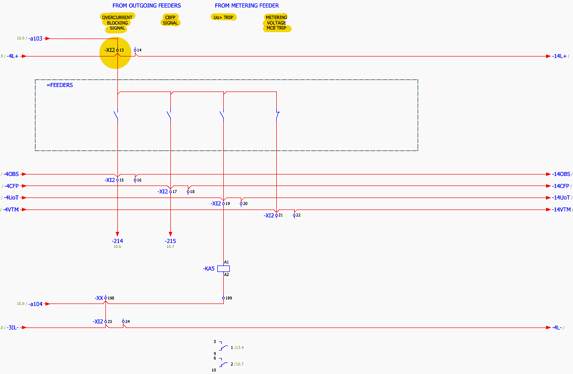
Another critical block is the ‘CBFP Signal’ (Circuit Breaker Failure Protection). If a relay issues a trip command but detects that the fault current is still flowing after a predefined time delay (indicating the VD4 breaker mechanically failed to open), it generates a CBFP signal. This signal is routed to upstream breakers, commanding them to trip immediately to clear the uncleared fault, overriding normal time-delay coordination.
Alarm Signals (=S01+C01&EFS/17) provide operators with non-critical but vital diagnostic information. These signals are typically aggregated and sent to a centralized SCADA system. The schematic outlines several distinct alarm paths.
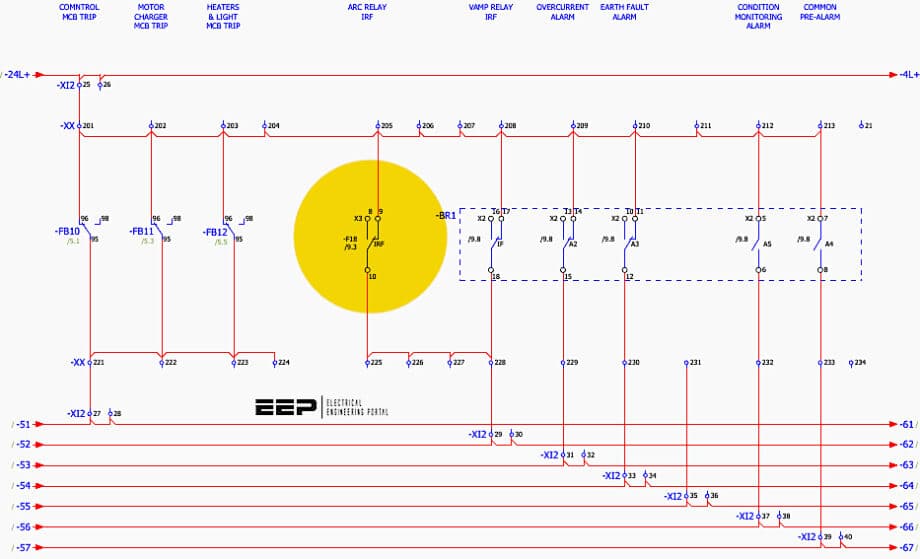
The ‘Control MCB Trip’ (-XI2 pins 25/26), ‘Motor Charger MCB Trip’, and ‘Heaters & Light MCB Trip’ alarms are generated by auxiliary contacts physically attached to the respective Siemens MCBs (-FB10, -FB11, -FB12). If any of these breakers trip due to an internal low-voltage short circuit, the contact closes, sending an alarm.
This allows maintenance to identify a dead control circuit before attempting to operate the switchgear.
Figure 14 – Alarm Signals
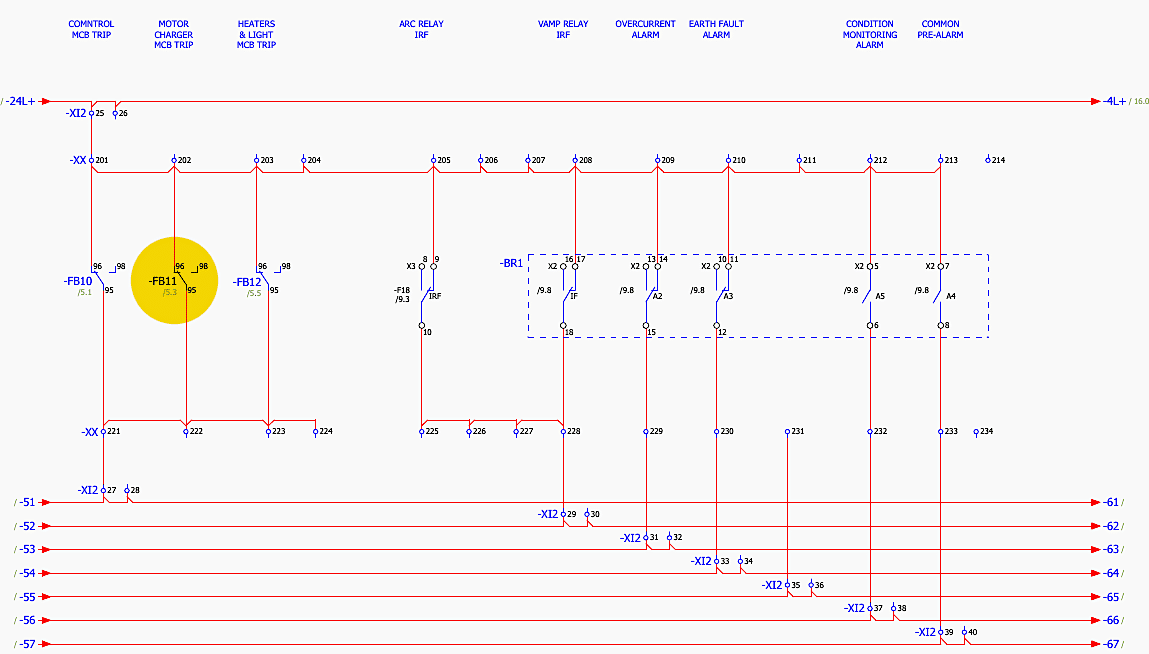
More severe alarms include the ‘Arc Relay IRF’ (Internal Relay Failure) and ‘VAMP Relay IRF’. Modern digital relays continuously run self-diagnostic routines on their CPU, memory, and A/D converters. If a hardware or software fault is detected internally, the relay drops out a dedicated IRF watchdog contact.
This immediately alarms the SCADA system that the specific panel is currently operating without protection, necessitating urgent intervention.
Additional alarms routed through the -XI2 terminal block include the ‘Overcurrent Alarm’ (a pre-trip warning that load is approaching the trip threshold), ‘Earth Fault Alarm’, and generalized ‘Condition Monitoring Alarm’ which could tie into SF6 gas pressure monitors (if applicable) or breaker wear algorithms computed by the REM5438M.
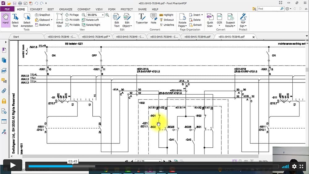
Suggested Course – Learn How to Depict Switchgear and Substation Single-Line Diagrams
7. Terminal Interconnections and Signal Routing
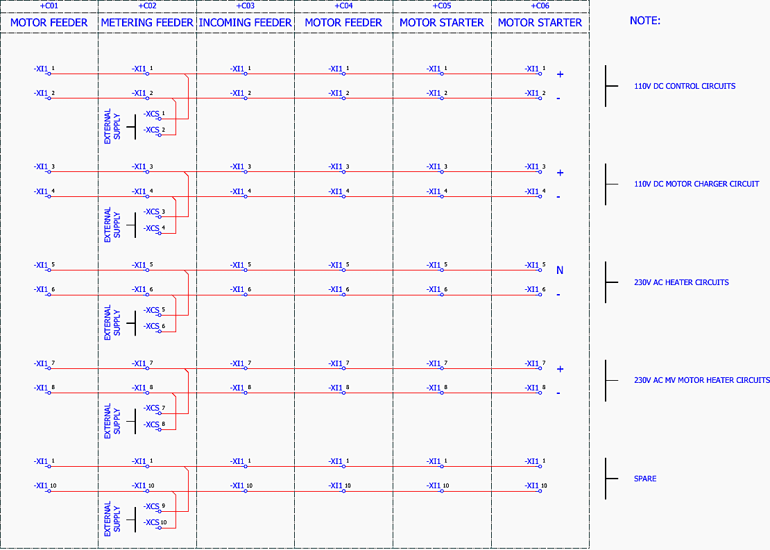
The physical realization of the schematic logic is achieved through the interconnection terminal blocks, primarily designated as: -XI1, -XI2, -XI3, -XI4, and -XI5. These blocks, detailed on sheets =S01&EFS/5 through =S01&EFS/13, act as the neural synapses of the switchgear, allowing cross-panel communication and external SCADA interfacing.
Terminal Block -XI1 serves as the primary conduit for auxiliary power. As documented on sheet =S01&EFS/5, this block distributes the lifeblood of the control system. Pins 1 and 2 carry the main 110V DC Control Circuit positive and negative rails, branching off to supply the protection relays and logic loops.
Pins 5 and 6 provide the 230V AC supply for the panel’s anti-condensation space heaters, ensuring the internal environment remains optimal. Pins 7 and 8 provide the secondary 230V AC supply specifically designated for the MV Motor Heater Circuits, which run out to the field to keep the 10kV stator windings dry.
Figure 15 – Interconnection Terminal -XI1
Terminal Block -XI2 is a densely populated block dedicated primarily to analog measurements, blocking logistics, and critical alarms.
Sheet =S01&EFS/6 reveals that pins 1 through 12 are allocated to the Metering Voltage circuits. These carry the scaled-down AC voltages from the TJP 4.0 VTs (phases L1, L2, L3, N, and the open-delta da-dn configurations used for zero-sequence voltage polarization).
This allows external utility meters or specialized power quality analyzers to tap into the busbar voltage. Moving down the block, pins 13/14 handle the aforementioned Overcurrent Blocking Signal.
Pins 15/16 interface with the VAMP Arc Protection system. Pins 17/18 carry the CBFP Tripping Signal, a vital last-resort command. Pins 19 through 24 route the Uo> Tripping Signal and the Metering Voltage MCB Trip Signal. The remainder of -XI2 (pins 25 through 48) forms the comprehensive alarm bus.
Terminal Block -XI3 handles the heavy mechanical interlocking logic. Sheet =S01&EFS/9 details these connections.
Pins 1/2 route the status of the Circuit Breaker Rack Out or Plug Off condition. Pins 3/4 and 11/12/13/14 are deeply integrated into the Earthing Switch (E.S.) Release Coil and the CB Truck Release Coil.
Figure 16 – Interconnection Terminal -XI3
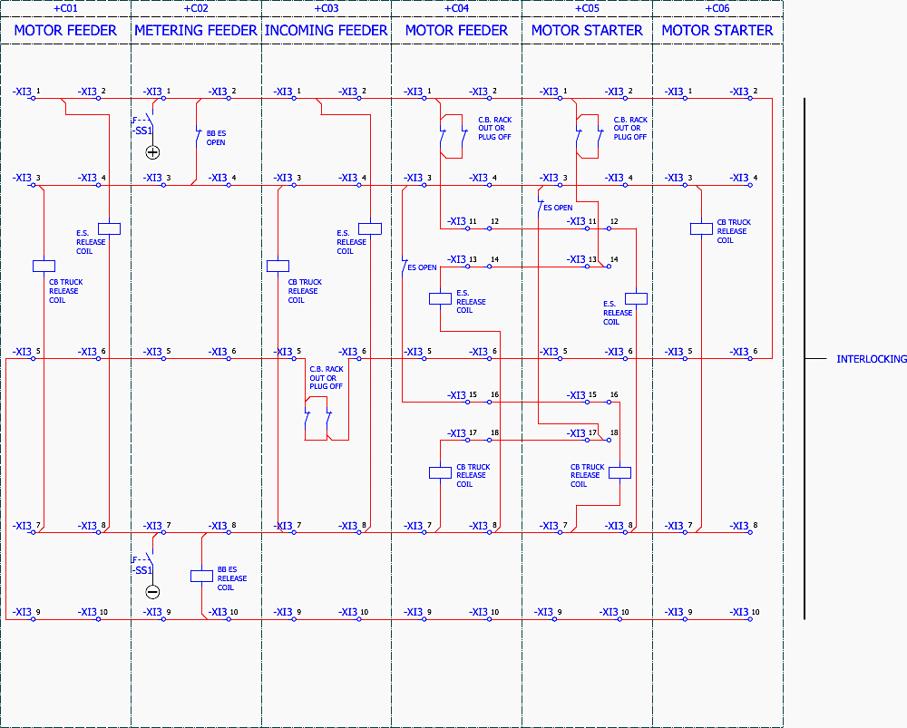
By routing these signals through -XI3, the panel allows for complex, multi-panel interlocking schemes. For example, a bus-tie breaker can physically block the earthing switch of a feeder panel from closing via connections through -XI3, ensuring absolute topological safety across the entire lineup.
Terminal Block -XI4 provides the macro-level operational status of the switchgear components. Sheet =S01&EFS/10 maps these points:
- Pins 1/2 report ‘CB ON’ (Main contacts closed), while pins 5/6 report ‘CB OFF’.
- Pins 9/10 indicate the ‘Truck in Service’ position, verifying the breaker is physically connected to the high voltage bus.
- Pins 11/12, 13/14 indicate ‘Truck in Test’, ‘ES ON’ (Earthing switch closed), and ‘ES OFF’.
- Pins 15/16 and 19/20 provide the external connection points for remote SCADA ‘CB ON-COMMAND’ and ‘CB OFF-COMMAND’. By applying 110V DC across these specific pins, a remote operator miles away can trigger the closing or tripping coils described earlier in section 5.
- Further down the block, pins 41-48 monitor the status of the metering truck,
- while pins 55-68 monitor specialized alarms like ‘CB Spring Discharged’ (meaning the breaker cannot perform a close-open-close cycle), ‘CB Mechanical Failure’, and ‘Autotrafo Buchholz Alarm’ (for panels equipped with liquid.
Figure 16 – Interconnection Terminal -XI4
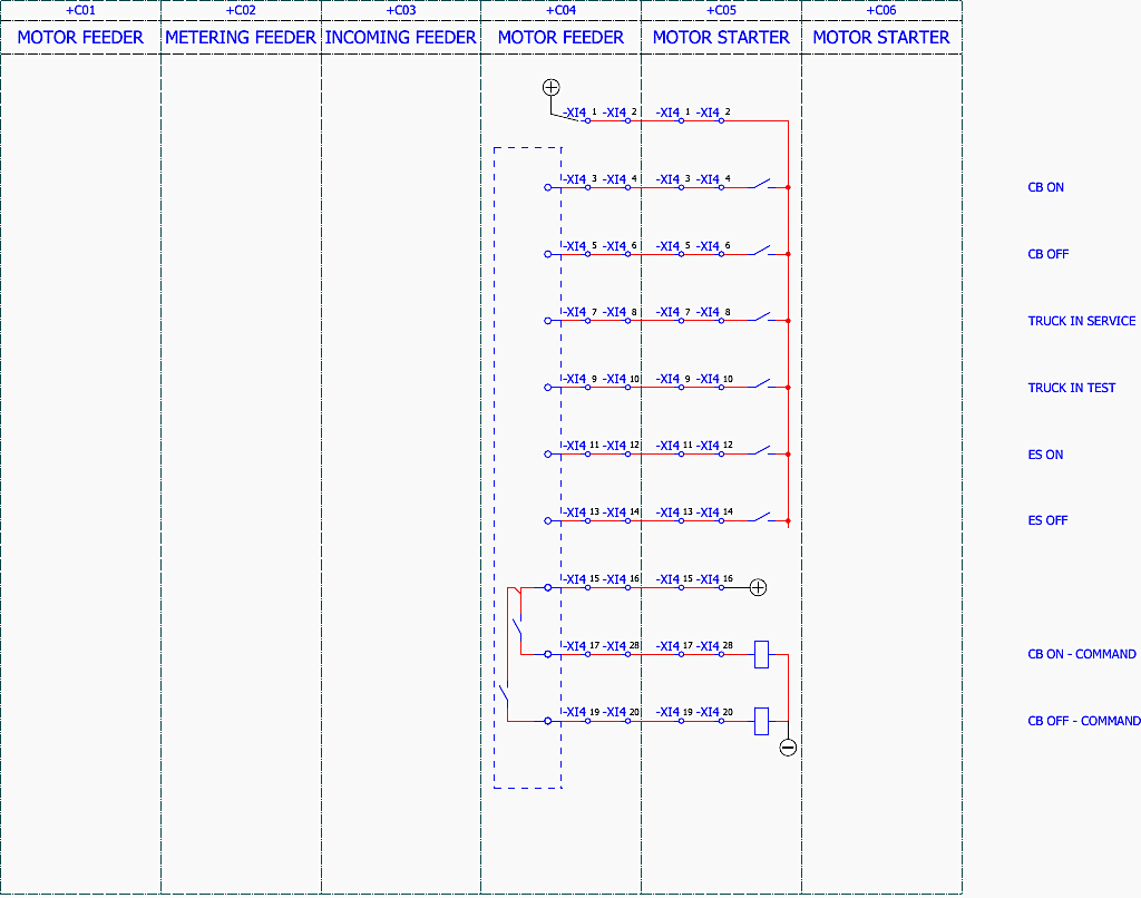
Terminal Block -XI5 handles the analog current transformer (CT) secondary circuits. Given the extreme danger of open-circuiting a live CT secondary, these terminal blocks are specialized shorting-type blocks.
Pins 1 through 6 route the highly accurate secondary currents from the TPU43.13 CTs (Phases L1, L2, L3, and Earth/Neutral residual) directly into the measurement inputs of the REM5438M and external metering devices.
Special care is indicated in the schematics to ensure the star-point grounding of these circuits is maintained at a single location to prevent ground loop interference in the protection logic.
Good Reading – Trip Signal and Trip Circuit Analysis of the 132kV Line-1 (=E01) Schematics (PDF included)
Trip Signal and Trip Circuit Analysis of the 132kV Line-1 (=E01) Schematics (PDF included)
8. Binary Input Mapping and Protection Relay Logic
The translation of physical switchgear states into digital logic is accomplished through the Binary Inputs of the protection relays. The detailed mapping of these inputs is located on sheets =S01+C01&EFS/10 and =S01+C01&EFS/11.
The protection relay (e.g., REM5438M) acts as the brain of the panel, but it requires ‘eyes’ to see the state of the breaker. This is achieved by wiring the auxiliary contacts of the VD4 breaker, the EK6 earthing switch, and various MCBs directly into the digital input cards of the relay.
A systematic review of the drawing shows the exact assignments. DI1 is assigned to ‘CB IN TEST POSITION’. When the breaker is racked out, a microswitch closes, applying 110V DC to DI1. The relay’s software now registers the breaker is in test mode, which automatically alters the relay’s behavior, it may disable specific trip outputs or enable logic testing algorithms.
Figure 17 – Binary Inputs of Protection Relay
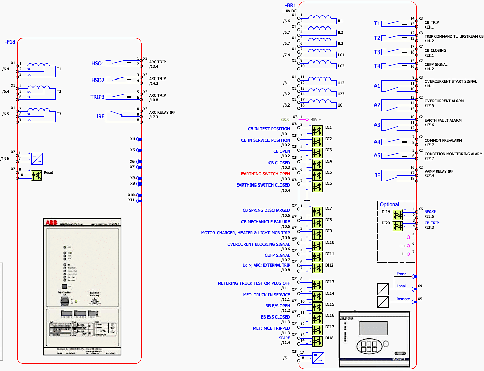
DI2 monitors the ‘CB IN SERVICE POSITION’. It is a critical safety parameter that DI1 and DI2 should never be active simultaneously; if they are, the relay software will flag a discrepancy error.
The actual open/closed status of the primary contacts is read via DI3 (‘CB OPEN’) and DI4 (‘CB CLOSED’). This provides the relay with positive feedback. If the relay issues a trip command via its output contacts to the -Y2 coil, it immediately starts a timer. It expects to see DI4 drop low and DI3 go high within approximately 50 milliseconds.
The safety topology is further reinforced by DI5 (‘EARTHING SWITCH OPEN’) and DI6 (‘EARTHING SWITCH CLOSED’). The relay uses these inputs to inhibit motor starting logic. It is impossible for the relay to issue a remote close command to the motor if DI6 is true. DI7 reads the ‘CB SPRING DISCHARGED’ status.
Figure 18 – Binary inputs scheme
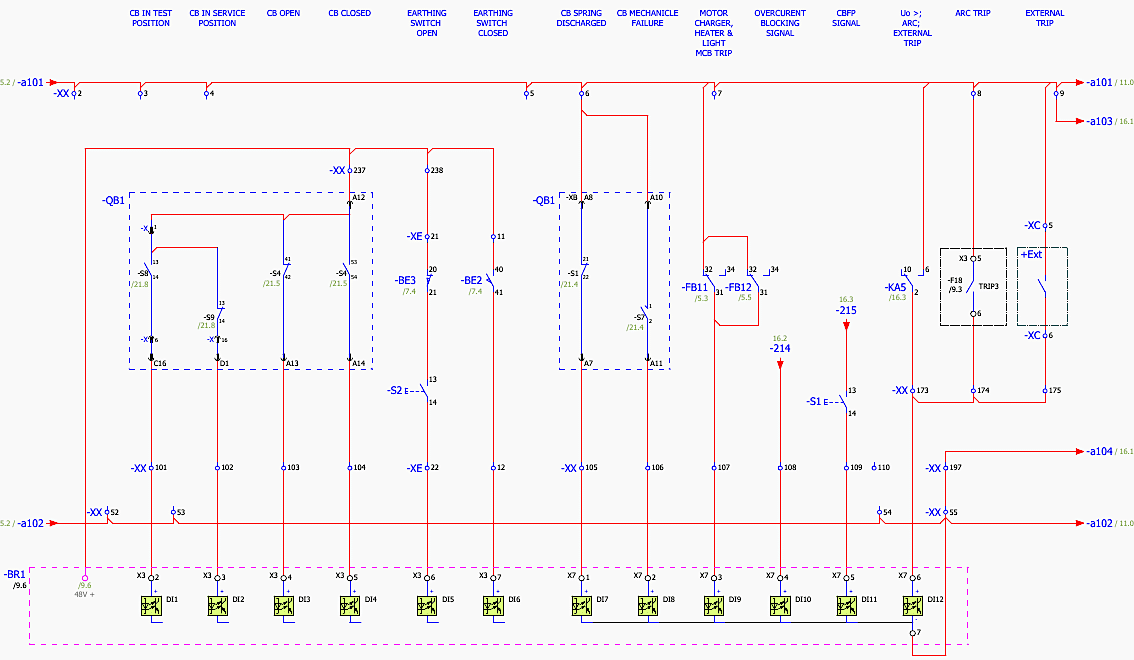
The VD4 mechanism relies on a heavily tensioned mechanical spring to snap the vacuum interrupters open and closed. If the charging motor fails, the spring will eventually discharge. DI7 warns the relay that the breaker lacks the stored mechanical energy required for operation.
More complex fault scenarios are monitored via the higher-numbered digital inputs.
DI11 receives incoming ‘CBFP SIGNALS’ from other panels. Finally, DI12 is an aggregate input for ‘Uo >; ARC; EXTERNAL TRIP’, acting as a master external kill switch that bypasses normal software delays.
Figure 18 – Medium voltage draw-out vacuum circuit breaker, type VD4
9. Findings, Inconsistencies and Points to Verify
The set is a demonstration project, and several points would have to be resolved before it could be issued for construction. All of these are visible in the drawings themselves:
Verification #1
Panel naming does not agree between sheets. The structure identifier overview (&EAC/7, PDF 6) defines +C01 and +C02 as motor starter, +C03 motor feeder, +C04 incoming feeder, +C05 measuring panel, +C06 motor feeder. The total overview (PDF 11) agrees.
The column headings on all the interconnection sheets (PDF 12 to 20) instead read +C01 MOTOR FEEDER, +C02 METERING FEEDER, +C03 INCOMING FEEDER, +C04 MOTOR FEEDER, +C05 and +C06 MOTOR STARTER. The two conventions cannot both be right!?
Verification #2
The incoming feeder does not appear on the overview. The total overview single line (PDF 11) shows only five fields: +C06, +C05, +C03, +C02 and +C01. Location +C04, for which a complete schematic set exists (PDF 40 to 58), has no single-line field.
Verification #3
Two different CT types are specified for the same location. ASS24 400/1/1 A on the +C01 single line (PDF 21) versus TPU43.13+CD 1200/1/1 A on the overview (PDF 11, column 9).
Verification #4
Two different breaker types are named. The single lines specify VD4 24.12.25, 1250 A; the circuit breaker overview (PDF 38, title block area) is drawn for TYPE VM1.
Verification #5
Cubicle widths differ between drawings. The front view (PDF 8) dimensions the five cubicles as 800/640/650/800/650 mm; the foundation frame (PDF 10) shows five bays of 650 mm and a table entry FT = 650 mm.
Verification #6
Terminal numbering anomalies. On PDF 17 and 20 the CB ON – COMMAND pair is numbered -XI4:17 / -XI4:28 and -XI4:37 / -XI4:38 respectively, so the first sheet appears to use 28 where 18 would be expected.
On PDF 12 the spare pair in the -XI1 group is labelled -XI1:1 and -XI1:10, duplicating terminal 1.
Verification #7
Sheet titles do not match sheet content in the -XI4/-XI5 group. =S01&EFS/11 (PDF 18) is titled Interconnection Terminal –XI4 but carries -XI5 terminals; =S01&EFS/13 (PDF 20) is titled -XI5 but carries -XI4:21–40.
Verification #8
The export is incomplete relative to the table of contents. The contents list 70 pages and the cover states 71, while this PDF contains 68. The sheets &EEB/3 (IEC 61355) and =S01+C04&EFA/2 (Symbol Overview IEC_ED_ESS) are listed but not exported.
Verification #9
The parts list is not complete. No part numbers are assigned to any medium-voltage apparatus – the breakers, current and voltage transformers, earthing switches and protection relays all appear on the schematics but not in the bill of materials.
Verification #10
Spelling in the function texts. Several headings contain typographic errors that would be carried into the wiring labels if used as-is: Triping Circuit, CB MECHANICLE FAILURE, OVERCURENT BLOCKING SIGNAL, COMNTROL MCB TRIP, diagramm.
Good Reading – Substation control and monitoring systems: The eyes and ears of every power system
Substation control and monitoring systems: The eyes and ears of every power system
10. Conclusion and Switchgear Summary
The EPLAN schematic analysis of the 10kV Motor Control Centre reveals a highly sophisticated, deeply layered approach to medium voltage power distribution. The design documented in project 02122010-007 exemplifies modern engineering standards, utilizing redundant fail-safes, high-speed optical arc protection, and comprehensive electromechanical interlocking.
By analysing the individual sheets, from the physical layout of the +C01 to +C06 panels down to the signal routing through terminal blocks -XI1 to -XI5, a clear operational philosophy emerges.
The system is designed such that no single point of failure – be it a faulty MCB, a broken trip coil wire, or an operator attempting to bypass standard procedures, can result in catastrophic equipment damage or personnel injury.
Finally, the exhaustive blocking, alarming, and binary input matrices provide the localized protection relays and remote SCADA systems with unparalleled situational awareness. This 10kV MCC stands as a prime example of resilient electrical infrastructure design.
Good Reading – In-Depth Schematic Analysis of the 1000A Low-Voltage Motor Control Center (MCC)
In-Depth Schematic Analysis of the 1000A Low-Voltage Motor Control Center (MCC)
11. Deep Technical Component Analysis
Detailed Component Operational Physics And IEC Standards Compliance
To fully grasp the implications of the schematics analyzed above, a deep dive into the operational physics of the primary components is required, cross-referenced with the relevant International Electrotechnical Commission (IEC) standards that govern their design and application within this specific 10kV Motor Control Centre.
11.1 The Vacuum Circuit Breaker
The Vacuum Circuit Breaker (VD4 24.12.25 1250A) in the Context of IEC 62271-100
The ABB VD4 breaker specified in panels +C01, +C03, +C04, and +C06 is not merely a mechanical switch; it is a complex kinetic energy storage device and plasma suppression system. When the -Y2 shunt trip coil is energized by the protection relay (as traced through sheet =S01+C01&EFS/13), it unlatches a mechanical sear.
This plasma is highly conductive and allows the fault current to continue flowing momentarily.
Video Lesson – Circuit Breaker (52)
However, vacuum interrupters utilize specialized contact geometries, such as transverse magnetic field (TMF) or axial magnetic field (AMF) designs.
The current flowing through the contacts generates a powerful magnetic field that forces the arc plasma to spin rapidly around the perimeter of the contact surface. This spinning prevents localized overheating and gross melting of the copper-chromium contact material.
As the alternating current approaches its natural zero-crossing point, the energy sustaining the plasma drops to zero.
The rigorous testing dictated by IEC 62271-100 ensures that the VD4 can perform this fault-clearing operation repeatedly without degrading its nominal 1250A continuous current carrying capacity.
Further Study – Comprehensive Masterclass: Learn Line Protection Panel Schematics (UK, US, EU, Middle East, and Asian Standards)

11.2 Current Transformer Saturation and Protection Selectivity
The accuracy of the entire tripping logic relies entirely on the fidelity of the current transformers. The specified TPU43.13 unit is a dual-core cast resin transformer. The critical specification for the protection logic is the 5P10 rating of the secondary core. In protection engineering, it is well understood that during a severe short circuit, the primary current can spike to tens of thousands of amperes.
This high primary current generates a correspondingly high magnetic flux in the iron core of the CT. If the core does not have enough cross-sectional area or is made of inferior steel, it will magnetically saturate.
When a CT saturates, the secondary current waveform becomes severely distorted, effectively ‘clipping‘ the peaks. A protection relay reading a saturated CT secondary will ‘see’ a much smaller current than is actually flowing in the primary circuit, leading to delayed tripping or a complete failure to trip. The ‘10‘ in the 5P10 designation guarantees that the CT will maintain an accuracy limit factor of 10.
This specific characteristic is what allows the REM5438M relays to utilize high-speed instantaneous overcurrent elements (ANSI 50) with confidence, knowing the CT will faithfully reproduce the fault current magnitude without saturating in the critical first few cycles.
Useful Tool – Current transformer (CT) saturation calculator
11.3 Optical Arc Fault Protection
Optical Arc Fault Protection Physics (VAMP 255 / REA 101)
Traditional overcurrent protection relies on detecting an increase in current. However, an internal arc fault within the metal-clad switchgear presents a unique challenge. An arc fault is a highly chaotic, resistive plasma discharge. The resistance of the arc itself limits the fault current.
In many cases, the fault current of a devastating internal arc flash may be lower than the starting inrush current of a large 10kV motor.
An electric arc generates intense light across the visible and ultraviolet spectrum.
Optical sensors (lens or bare fiber optics) are routed throughout the busbar, circuit breaker, and cable compartments. These sensors are continuously monitored by the arc protection relay. Because camera flashes or sunlight could cause false tripping, the relay employs a dual-verification condition.
Figure 19 – Optical Arc Fault Protection
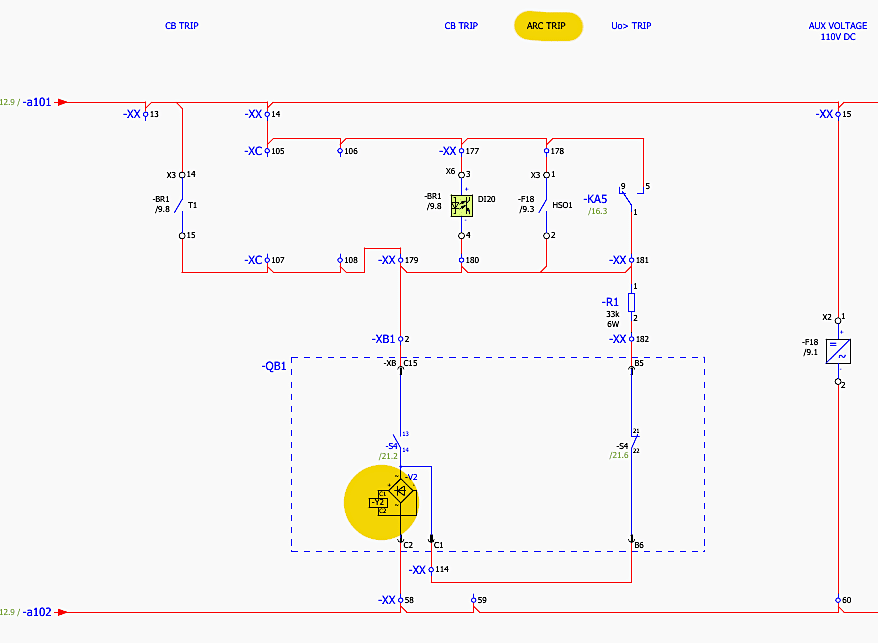
It simultaneously monitors the current transformers for an abrupt step-change in current. If the relay detects a large flash of light AND a sudden surge in current simultaneously, it bypasses all software delays and fires a dedicated, high-speed insulated gate bipolar transistor (IGBT) output contact directly into the -Y2 trip coil circuit (as seen on sheet =S01+C01&EFS/13).
This drops the total clearing time to less than 2 milliseconds for the relay logic, limited only by the mechanical opening time of the VD4 breaker itself. This ultra-fast operation limits the incident energy of the arc, protecting personnel and preventing the switchgear from blowing apart from the internal pressure wave.
Further Study – The art of arc-protection relaying in MV applications
11.4 The Criticality of the EK6 Earthing Switch Making Capacity
The interlocking logic discussed in Section 5 prevents the EK6 earthing switch from closing when the breaker is in the service position. However, human error or complex induced voltages from adjacent parallel lines can still create dangerous scenarios.
If a maintenance worker closes the EK6 earthing switch onto a line that is still energized from a remote source, the resulting short-circuit current will immediately jump to the switchgear ground bus. An ordinary disconnect switch would be blown open by the immense electromagnetic repulsion forces generated by the fault current, drawing an unconfined arc that would likely be fatal to the operator holding the handle.
This allows the EK6 to safely conduct the full 25kA short-circuit current for 1 second, maintaining mechanical integrity and containing the fault until upstream protection clears it. The operator is shielded by the earthed metal enclosure, and the switch itself survives the event, albeit requiring inspection before re-use.
Learn more – Medium voltage switches for isolation and earthing (applications and IEC 62271 ratings)
Medium voltage switches for isolation and earthing (applications and IEC 62271 ratings)
11.5 Digital Relay Binary Input Debouncing and Signal Integrity
The binary inputs (DI1 through DI18) on the protection relays are the interface between the noisy, high-voltage physical world of the switchgear and the low-voltage microprocessor environment of the relay. The 110V DC control voltage traversing the auxiliary contacts (-S1, -S2, -BX5) is subjected to significant electromagnetic interference (EMI).
When a large primary breaker opens, or when inductive coils like -Y2 or -Y3 are de-energized, massive voltage spikes (inductive kickback) are generated in the control wiring. If the digital inputs were simple digital gates, these EMI spikes would cause chaotic, false state changes, tricking the relay into thinking the breaker was rapidly opening and closing.
Furthermore, the relay software employs debouncing algorithms. When a mechanical contact closes, it physically bounces several times on a microscopic level before settling. The relay software requires the binary input to remain in a stable ‘high’ state for a programmed duration (e.g., 20 milliseconds) before it accepts the state change as valid.
This prevents the bouncing contacts from triggering multiple, erroneous logic events.
Further Study – 400kV Reactor Troubles Circuit Schematics: Technical Analysis
400kV Reactor Troubles Circuit Schematics: Technical Analysis
12. Attachment (PDF): DC Grid Protection Guide: Fault Analysis and System Design
Download: DC Grid Protection Guide: Fault Analysis and System Design (for premium members only):
Related electrical guides & articles





Edvard Csanyi
Hi, I'm an electrical engineer, programmer and founder of EEP - Electrical Engineering Portal. I worked twelve years at Schneider Electric in the position of technical support for low- and medium-voltage projects and the design of busbar trunking systems.I'm highly specialized in the design of LV/MV switchgear and low-voltage, high-power busbar trunking (<6300A) in substations, commercial buildings and industry facilities. I'm also a professional in AutoCAD programming.
Profile: Edvard Csanyi