
Estimated Study Time: 9 minutes
Shielding and Grounding Importance
For several years, the increased application of solid-state devices for protective relaying and control and for electronic equipment, such as audio tones, carrier and microwave equipment, event recorders, and supervisory control equipment, in EHV substations has resulted in many equipment failures.
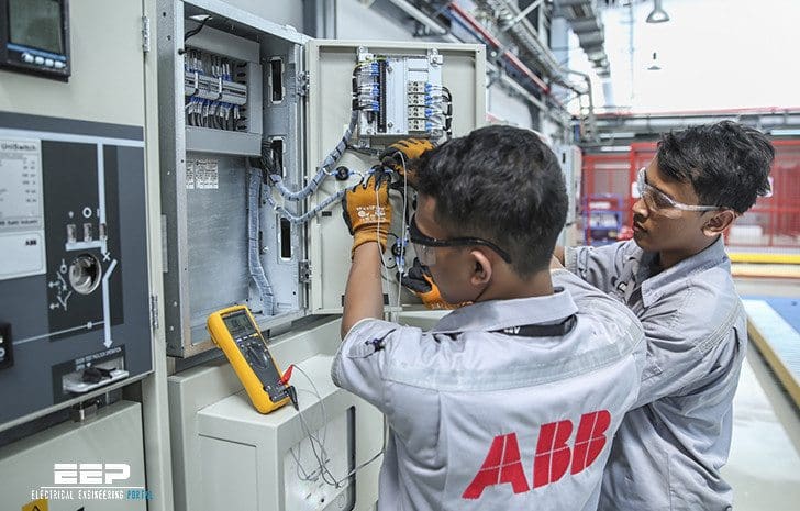 Shielding and Grounding Practices for Control Cables in EHV Substations (photo credit: ABB)
Many of these failures have been attributed to transients or surges in the control circuits connected to the solid-state devices. Failures due to transients or surges have been experienced even with conventional electromechanical devices.
The failures being experienced are attributed to the use of EHV (345 kV and higher voltage levels) as well as the presence of unusually high short-circuit currents.
The transient magnetic fields associated with these high-frequency surge currents are both electrostatically and magnetically coupled to cables in the area. Induced voltages have been reported to be as high as 10 kV in cables without shielding, and the frequencies of these induced voltages have been reported to be as high as 3 MHz.
In order to avoid insulation breakdown at 10kV crest and possible false operation of relays, it is important that station design includes necessary precautions to limit the undesirable surges and control circuit transients to an acceptable minimum.
In any station design there are several precautions that can be taken. All cable circuits that are used in a substation should be run radially, with each circuit separated from any other circuit and with both supply and return conductors contained within the same cable.
If a conductor is routed from the control house to a point in the switchyard with the return circuits following different paths, loops may be formed that are inductive and are subject to magnetically induced voltages.
However, when the two conductors involved are both affected by the same field, the voltage appearing between them at the open end should be essentially zero.
Because of ground-mat potential differences and longitudinally induced voltages in the radial circuits, proper cable shielding is necessary to maintain lowest possible voltages on the cable leads. The cables that require shielding include control, current, and potential transformer circuits. The shield should be of as low resistance as possible, and it should be connected to the ground grid at least at both ends.
To reduce penetration of a magnetic flux through the nonferrous shield (lead, copper, bronze, etc.), a current must flow in the shield to produce a counterflux, which opposes the applied flux.
Ground-grid conductors should be placed in parallel to and in close proximity to the shield to maintain as low a resistance between the ends as possible and also to form a small loop to reduce the reactance between ground and the shield. Without close coupling of the conductor and ground shield, the propagation time of the two paths could differ so that a voltage impulse could arrive at the receiving end with a time difference, hence causing an unwanted voltage difference.
The bare copper cable should run as closely as possible to the cable run. The heavy cable functions to provide a low-resistance path in an attempt to prevent heavy fault currents from flowing in the shield and to reduce reactance between ground and shield.
In order to limit induced voltages, the control-cable runs should be installed, where possible, at right angles to high-voltage buses. Where it is necessary to run parallel to a high-voltage bus for any appreciable distance, the spacing between cables and high-voltage buses should be made as great as possible. Distances of at least 50 ft should be maintained.
It is further considered good practice to have both current transformer and potential transformer leads installed with the ground for the secondary wye neutral made at the control-house end rather than at the switchyard end. Any rise due to induced voltages will be concentrated at the switchyard and will ensure operator safety at the control switchboard in the control house.
The shield can be grounded by using a flexible tinned copper braid of from 1/2 to 1 in wide. The shielded-cable outer insulation is peeled back, exposing the sheath. The 1-in braid is wrapped around the sheath and soldered carefully to it. The other end of the braid is connected to a lug, and solder should be run over the lug to the braid connection. The lug is then bolted securely to the ground bus bar.
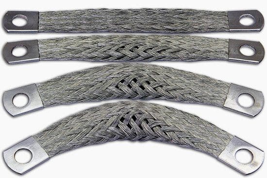
The flexible copper braid circuits should be kept as short as possible and should be run directly to the ground bus without any bends, if possible.
It should be pointed out that the shields should be grounded at multiple points rather than at a single point, because of the tendency to lose any advantage from single-point grounding at 50 kHz and above. As an example, assume that one input and one output terminal of a system are grounded, each at different points on a common ground plane. A small noise voltage will usually exist across these ground points because of currents flowing in the finitely conductive ground plane.
Removal of one of the ground connections achieves a single-point ground only for dc and low frequency signals. At higher frequencies, ground loops will be created by capacitance coupling.
Frequencies below 50 kHz are considered the arbitrary crossover point for single-point grounding.
At EHV, the transient voltages above 50 kHz represent the more serious problem; for this reason, all cable shields should be grounded at least at two points. It should be noted that shielding of control cables is normally provided for substations operating at voltage levels of 138 kV and above.
Reference // Standard Handbook for Electrical Engineers By Donald G. Fink, H. Wayne Beaty (Purchase hardcover from Amazon)
Related electrical guides & articles


Edvard Csanyi
Hi, I'm an electrical engineer, programmer and founder of EEP - Electrical Engineering Portal. I worked twelve years at Schneider Electric in the position of technical support for low- and medium-voltage projects and the design of busbar trunking systems.I'm highly specialized in the design of LV/MV switchgear and low-voltage, high-power busbar trunking (<6300A) in substations, commercial buildings and industry facilities. I'm also a professional in AutoCAD programming.
Profile: Edvard Csanyi

Dear’s
I hope you will be in good your health when you find this conversation.
please let me know the procedure for Power transformer grounding and high voltage cable (115Kv ,380Kv ) sheath grounding in photos form .
Best Regards
Muhammad waseem
Dear Mr. Edward,
Its great job you have done to our electrical engineering field.
I am appreciating your beautiful work and the way you are writing technical articles it’s really wonderful and interesting.
Best Regards,
Kannan Sukumaran
https://electrical-engineering-portal.com/