
Estimated Study Time: 22 minutes
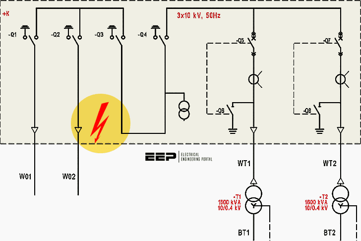
Short-circuit in electrical systems
If you ask any electrical design engineer what is the most time consuming and critical required in short circuit analysis, he/she would say that it’s obtaining available data. The less data that is assumed, the better and more accurate the results. There are conditions when most of the data may initially have to be estimated, such as when designing a new system.
 What do you need for short-circuit calculations? The less you assume, the better!
As the system becomes finalized, specific equipment data may be available and the results are more pertinent.
On existing systems, the amount of estimated data is greatly reduced. An up-to-date single-line diagram is needed. If one is not available, site inspection is required to determine switchgear and load center connection points. There may be cases where no information exists regarding the interconnection of plant loads back to the utility supply.
One great value of the short-circuit study is therefore an up-to-date single-line diagram.
In the discussion in first part of this article (Utility sources), the available data used for short-circuit calculations that can be obtained from equipment nameplates is noted by an *. Other data required will have to be itemized and requested or gathered separately. The data is then converted to ohms or per-unit ohms before it can be used in the analysis.
- Utility sources
- Generators
- Synchronous motors
- Induction motors
- Transformers
- Reactors
- Capacitors
- Static regenerative drives
- Breakers, contactors, and current transformers
- Cables
- Transmission lines
1. Utility sources
The equipment impedance data for the utility source must be obtained from the utility company. When requesting the data, specify at what point the source contribution equivalent is to be desired, form desired (per-unit, MVA, or amperes), base voltage used for the calculation, X/R ratio at the point specified, and if data desired is for three-phase or three-phase and line-to-ground calculations.
A single-line diagram sketch is often helpful in defining the point of the equivalent. Most utilities do not include the industrial user as a source of short-circuit current unless in-plant generation is present.
If the plant has more than one connection point, then a more complex equivalent is required and part of the utility may have to be represented.
Typical forms of the data received from the utility is given below:
- MVA with phase angle or X/R ratio.
(Requires voltage level at which MVA was calculated) - Fault current with phase angle or X/R ratio.
(Requires voltage level at which current is calculated) - Resistance and reactance in ohms.
(Requires voltage level at which ohms are calculated) - Per-unit resistance and reactance.
(Requires voltage level and MVA base, usually 100 MVA) - Percent resistance and reactance.
(Requires voltage level and MVA base, usually 100 MVA)

2. Generators
The data available from the machine nameplate is not significantly complete for an accurate short-circuit calculation.
Typical data on the nameplate is as follows:
- Manufacturer and serial number
- Rated MVA* and voltage*
- Rated frequency and machine speed
- Rated current and field voltage
The machine nameplate data required for short-circuit calculations is noted by an *.
On machines built in the early 1900s, the subtransient impedance was defined differently from what it is today. A recalculation by the vendor could result in different impedance values as compared to what was originally furnished.
The following data is required for short-circuit calculations:
- X”dv – rated voltage (saturated) direct-axis subtransient reactance (first-cycle and interrupting calculations)
- X’dv – rated voltage (saturated) direct-axis transient reactance (relaying time calculations)
- X2V – rated-voltage (saturated) negative sequence reactance (used to calculate X/R ratio, and in unbalanced fault calculations)
- TA3 – rated-voltage generator armature time constant in seconds, or Ra – armature resistance, (used to calculate X/R ratio)
- Short-circuit current decrement curve (not required, but will be useful in relaying time calculations)
- X0 – zero sequence reactance (used in unbalanced fault calculations for grounded generators)
One item not supplied as part of the generator nameplate or data sheet that may be required for relaying time calculations is the type of voltage regulator used with the generator.

3. Synchronous motors
The data required for synchronous motors is the same as that furnished for generators. Machine nameplate data may not be sufficiently complete for an accurate short-circuit analysis.
Typical data on the nameplate is as follows:
- Manufacturer and serial number
- Rated MVA* and voltage*
- Rated frequency and machine speed
- Rated current and field voltage
The machine nameplate data required for short-circuit calculations is noted by an *.
Some manufacturers may only furnish one transient or subtransient impedance for motors, which is usually the rated voltage X”dv value that is desired for short-circuit calculations.
The following data is required for short-circuit calculations:
- X”dv – rated voltage (saturated) direct-axis subtransient reactance (first-cycle and interrupting calculations)
- X’dv – rated voltage (saturated) direct-axis transient reactance (relaying time calculations)
- X2V – rated-voltage (saturated) negative sequence reactance (used to calculate X/R ratio and unbalanced faults)
- TA3 – rated-voltage generator armature time constant in seconds, or Ra – armature resistance, (used to calculate X/R ratio)
- Short-circuit current decrement curve (not required, but may be useful in relaying time calculations)
- X0 – zero sequence reactance (used in unbalanced fault calculations for grounded motors. Most wye connected motors are not connected to system neutrals)
One item not supplied as part of the motor nameplate or data sheet that may be required for relaying time calculations is the type of voltage regulator used with the motor. Most of the present day regulators are of the potential source type and do not supply sustained short-circuit currents.

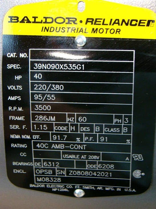
4. Induction motors
Some data required for short-circuit studies that include induction motors is on the motor nameplate. But the nameplate data is not sufficiently complete for an accurate short-circuit calculations.
Typical data on the nameplate is as follows:
- Manufacturer and serial number
- Rated HP or MVA* and voltage*
- Rated frequency and motor speed*
- Rated current and NEMA code letter*
Data required for short-circuit calculations is noted by an *.
Machine impedances are seldom furnished on a separate data sheet. However, if a data sheet is available, the manufacturer usually specifies the locked-rotor current that can be used to estimate the motor subtransient impedance.
More detailed impedance data is available at a cost, but is usually not justified. Different impedance data is furnished for the motor at both stall and running conditions and the resistances furnished may not include the one required for short-circuit calculations.
Data for smaller motors is usually estimated because the cost of obtaining this information is not justified.
5. Transformers
Transformer nameplates usually provide most of the data required for short-circuit calculations.
Typical data on the nameplate is as follows:
- Manufacturer and serial number
- Rated MVA* and frequency
- Rated primary and secondary voltages*
- Rated current and taps available*
- Transformer percent impedance*
- Number of windings, winding connection and phase relationship* (needed for unbalanced fault calculations)
- Manufacturer test report.
The nameplate data required for short-circuit calculations is noted by an *.
Note that the transformer nameplate data is given as a percent impedance and not percent reactance and is generally given on the self cooled rating unless otherwise specified.
Some data sheets do provide the% resistance as a piece of data; otherwise, the % resistance is determined by:
or
The standard phase relationship of a delta-wye or wye-delta transformer is that the high-voltage side leads the low-voltage side by 30 degrees for positive phase sequence systems.
Note that one side of the transformer is selected as reference. With the reference established, the phase shift is applied following the general rule of “HV side leads LV side for positive sequence, and HV lags LV for negative sequence.”
Example of a delta-wye transformer
As an example, suppose that a delta-wye transformer has the HV winding selected as reference. Based on this choice of reference, the positive sequence LV side values will lag the positive sequence HV side values, and the negative sequence LV side values will lead the negative sequence HV side values.
There will be no shift of the zero sequence current since there is no path for this current component to flow. The zero sequence voltage is determined by the zero sequence impedance times the zero sequence current flow on each side of the transformer.

6. Reactors
The reactor nameplate usually provides most of the data required for short-circuit calculations.
Typical data on the nameplate is:
- Manufacturer and serial number
- Rated voltage* and frequency
- Rated current* and taps available*
- Reactor percent impedance*
- Reactor ohms* (not always provided)
- Percent voltage drop* (not always provided)
- Manufacturer test report
The nameplate data required for short-circuit calculations is noted by an *.
For example, the percent impedance is on the “through” kVA (volts × amps) of the reactor and for a three-phase reactor the through kVA is:
![]()
The impedance can also be determined from the voltage drop as follows:
Impedance in ohms = Volt drop in volts / IRated
The base for the percent voltage drop (when used) is line-to-line rated voltage. For a three-phase reactor, the “self” kVA is as follows:
![]()
7. Capacitors
The inclusion of capacitor data is usually not necessary under most conditions. Knowing capacitor contributions to short-circuit currents is important to determine the actual extent to which capacitors will affect the first-cycle calculations.
When a fault occurs, capacitor…
A capacitor in an AC system charges and discharges in a controlled manner every half cycle, based on the sinusoidal driving voltage and system impedances. When a fault occurs, the system voltage is suddenly changed and the capacitor discharges at a rapid rate, with a high discharge current. The current is greatest if the fault occurs when the capacitor is charged to the maximum at a voltage peak. Only the impedance between the capacitor and the fault limits the discharge current.
The current will “ring down” based on circuit resistance and reactance. The resistance provides damping and the interaction between the system reactance and capacitor determines the frequency of the oscillating current.
If inclusion of the capacitor data is required, the capacitors nameplate is complete for short-circuit calculations.
The data on the nameplate will be as follows:
- Manufacturer and serial number
- Rated voltage* and frequency
- Rated kvar*
The nameplate data required for short-circuit calculations is noted by an *.
The capacitor X/R ratio is not on the nameplate, but is generally very high and can be determined from the capacitor loss test sheet, if it is provided. If assuming the X/R ratio, a value from 200 to 300 should be acceptable, because the series cable resistance quickly overwhelms the capacitor resistance.
The length of cable to the capacitor bank is important and should be included.

8. Static regenerative drives
The inclusion of static regenerative drive data will be necessary in the first-cycle calculations. Note that non-regenerative drives are not sources of fault current and need not be considered. The rectifier transformer and drive motor size is required.
Typical data on the drive transformer nameplate is as follows:
- Manufacturer and serial number
- Rated voltage* and frequency
- Rated primary and secondary voltages*
- Rated current and taps available*
- Transformer percent impedance*
- Number of windings, winding connection and phase relationship
The nameplate data required for short-circuit calculations is noted by an *.
The drive transformer X/R ratio is not on the nameplate, but can be determined from the transformer test sheet or losses, if provided. Some data sheets do provide the percent resistance as a piece of data. Otherwise, the percent resistance is determined by:
or
Note that the drive transformer nameplate data is given as a percent impedance and not percent reactance. The reactance is determined once the percent resistance is known.
The motor data needed is the same as given for synchronous and induction motors above. For short-circuit calculations where the drive is modeled as an induction motor, the equivalent drive impedance should be greater than the typical impedance of an induction motor with the same rating.
9. Breakers, contactors, and current transformers
The inclusion of circuit breaker, contactor, or current transformer impedances is seldom done in short-circuit calculations. These impedances are more significant in low-voltage system analysis than for the higher-voltage systems.
For fractional horsepower motor loads, the thermal overload devices will have an impedance magnitude in ohms as compared to cable impedances in milliohms.

10. Cables
The connecting cables will not have any impedance data stamped on them. Data typically found on the cable includes the following:
- Manufacturer
- Rated voltage*
- Type of cable* and insulation type*
- Size of conductor*
In addition, the following data is required:
- Length
- Type of cable construction (1/C or 3/C)
- Number of cables in parallel and physical spacing
- Type of cable duct used (steel, fiber, cable tray, direct burial, etc.)
Data shown on cable and required for short-circuit calculations is noted by an *.
References usually provide positive sequence impedance, which is used in three-phase faults. For unbalanced faults, the zero sequence cable data is required and not usually provided in references.
The zero sequence impedances of cables differ from that of the positive and negative sequence and is dependent upon the physical configuration and the impedances of the ground return paths.
11. Transmission lines
The impedance data for connecting transmission lines should be based on the line configuration. Drawings or sketches showing wire size, type of conductor material, and conductor spacing are required.
In addition, circuit length, type and size of ground wire, and earth resistance must be obtained.
Sources:
- IEEE Recommended Practice for Calculating Short-Circuit Currents in Industrial and Commercial Power Systems
Related electrical guides & articles


Edvard Csanyi
Hi, I'm an electrical engineer, programmer and founder of EEP - Electrical Engineering Portal. I worked twelve years at Schneider Electric in the position of technical support for low- and medium-voltage projects and the design of busbar trunking systems.I'm highly specialized in the design of LV/MV switchgear and low-voltage, high-power busbar trunking (<6300A) in substations, commercial buildings and industry facilities. I'm also a professional in AutoCAD programming.
Profile: Edvard Csanyi

Very good article with nameplate descriptions of various equipment and information.
Very useful article. Thanks
Very good article about short circuit calculation. Certainly, this is a great help to young engineers and the experienced engineers as well in the actual practice. Thank you very much, Edvard. Best regards.
Thanks for the highly informative article. Can I have a typical short circuit calculation for a project for an industrial installation with Regenerative drive
best wishes
GREAT VERY INFORMATIVE…
Very informative and useful data in calculating sc. Please continue this kind of article for the benefit of those who has limited information in sc calculations.
Very interesting and useful Article!
Good morning Mr.Edvard
THANK YOU VERY FOR YOUR ACTIVITIES.
One question please : do you have any example related to any project contains the calculations steps to calculate the short circuit.if yes please send it me.
your cooperation is highly appreciated
Best regards
Nasser
thanks a lot for this upgrading fault calculation,
Thanks a lot.
Thanks a lot for this updated
Thanks a lot
I am impressive with this publications. May You continue to do more. Thanks
Very useful. keep updating.
Most advantageous.