
Estimated Study Time: 15 minutes
Solutions to optimize HV switchgear
Nowadays, when every cent is essential when building a substation, it is imperative to optimize each HV equipment without compromising functionality. This technical article deals with a few solutions to optimize high voltage switchgear in terms of space and cost. As an example, ABB’s solutions will be described and analysed. There are many manufacturers on the market that offer similar solutions (eg. Siemens, GE, Mitsubishi Electric, Toshiba).
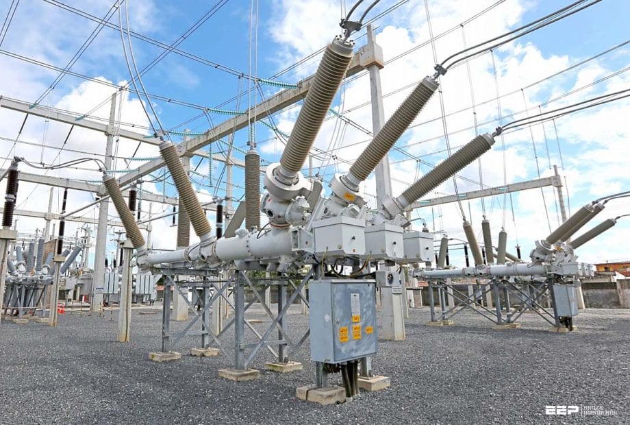 How to shrink three-phase AC high voltage switchgear and optimize cost and space (photo credit: ABB)
A switchgear installation contains all the apparatus and auxiliary equipment necessary to ensure reliable operation of the installation and a secure supply of electricity. Three-phase AC high-voltage switchgear installations with operating voltages of up to 800 kV are used for distributing electricity in towns and cities, regions and industrial centres, and also for power transmission.
The voltage level employed is determined by the transmission capacity and the short-circuit capacity of the power system.
Outdoor switching stations are used for all voltage levels from 52 to 765 kV. They are built outside cities, usually at points along the cross-country lines of bulk transmission systems.
Solutions and optimisation
- Compact outdoor switchgear installations
- Hybrid switchgear installations
- Prefabricated, modular transformer substations
1. Compact outdoor switchgear installations
A significant step toward reducing the space requirements of switchgear installations has been made by combining primary devices into more and more compact multifunctional switchgear units. This concept is not new and has already been implemented many times in applications such as outdoor switchgear installations with draw-out circuit-breakers.
The implementation of non-conventional current and voltage transformers now makes it possible to combine a large number of functions on one device bench. As a result, a range of combination switchgear has been developed in the last ten years.
Only the busbars and, depending on the basic design, the associated busbar disconnectors are installed outdoors.
All new HV switchgear components are distinguished by consistent integration of non-conventional sensors (in this case primarily current and voltage sensors), processor controlled mechanisms and connection to the bay control with fibre optics.
This yields the following:
- Increased availability,
- Less space required,
- Shorter project runtimes, and
- Extended maintenance intervals with a significant increase in ease of maintenance.
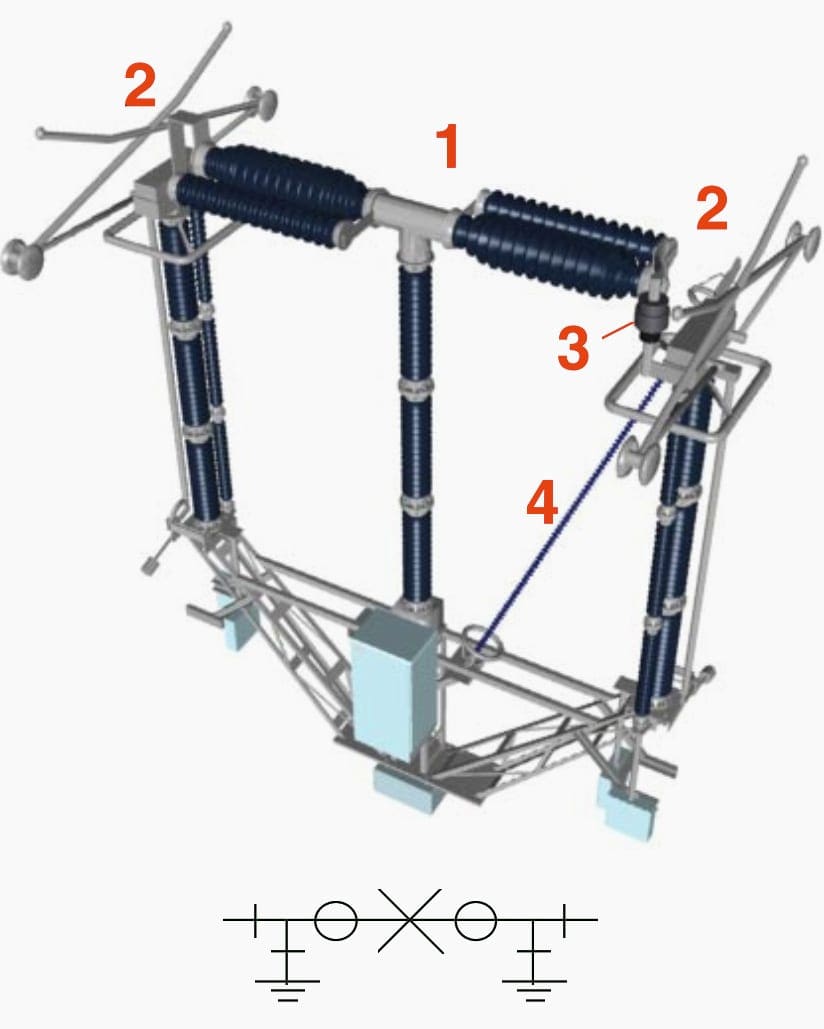
Figure 1 shows a design for compact outdoor switchgear installations for Un ≤ 145 kv with transverse circuit-breakers and integrated SF6 current transformers. The illustrated compact and prefabricated switchgear with prefabricated busbar connections makes it easy to set up simple secondary substations and H-configurations economically and quickly.
The circuit is disconnected on both sides of the circuit-breaker by the module moving to the side.
Where,
- 1 – Circuit-breaker
- 2 – Current transformer
- 3/4 – Disconnector and earthing switch, if required
- 5 – Surge arrester can replace the post insulator
An example of the layout of a simple H-configuration with these modules is shown in comparison to a conventional H-configuration in Figures 2 and 3. Dispensing with busbars and outgoing-feeder disconnectors allows smaller dimensions in comparison to conventional outdoor installations.
Conventional design of a high voltage switchgear
| Total Area | 2600 m2 |
| Switchgear installation | 930 m2 |
| Earthing system | 3700 m2 |
Compact design of a high voltage switchgear
| Total Area | 1200 m2 |
| Switchgear installation | 300 m2 |
| Earthing system | 1000 m2 |
Another variation of a compact switching module for use up to 170 kV is shown in Figure 4. The disconnector functions are realized with a draw-out circuit-breaker. This means that the conventional disconnectors are replaced by maintenance-free fixed contacts and moving contacts on the circuit-breaker.
An option is to install conventional or optical current and voltage transformers and earthing switches. The circuit-breaker can be simply withdrawn for maintenance, or if necessary, quickly replaced by a spare breaker. The main advantages here are also significant space savings, smaller bases, steel frames and reduced cabling requirements.
This switching module is particularly suited for single busbars and H-configurations.
Where,
- Draw-out circuit-breaker,
- Circuit-breaker rails,
- Disconnector isolating contact, fixed side (forms the isolating distance for circuit-breaker when withdrawn), and
- Current transformer
Figure 5 shows a compact switching module for applications of up to 550 kV. It is a combination of a circuit-breaker with one or two non-conventional current transformers installed on the interruptor chambers and two pantograph disconnectors. This compact design is only possible using very small non-conventional current transformers.
The current transformer signals are conducted through the tension insulators via fibre-optic cables to the control cubicle. Such compact modules make it possible to reduce the surface area required for an outdoor installation by up to 55 %.
This concept is particularly suitable for installations in 1 ½ circuit-breaker design.
Where,
- Circuit-breakers of up to 550 kV,
- Disconnectors on both sides (earthing switch possible),
- Optical current transformer, and
- Tension insulator for fibre optics
Comparison: 500 kV outdoor switchgear installation
Figure 6 shows a comparison of a conventional 500 kV outdoor switchgear installation in 1 ½ circuit-breaker design with an installation in compact design using the modules described above. This makes the saving in surface area with the same functionality particularly clear.
2. Hybrid switchgear installations
Two insulation media, i.e. air and SF6, can be combined in high-voltage installations with the modular principle of SF6-isolated installations. This type of installation is referred to as a “hybrid installation”.
Figure 7 shows a hybrid switching device for voltage levels of up to 550 kV. The name “Plug And Switch System” (PASS) – indicates the philosophy of this concept. The highly integrated components allow that in new installations and in retrofit projects compact PASS units can be erected and comissioned quickly.
These units are connected to the secondary equipment of the substation by prefabricated cable links, which include both the auxiliary voltage supply cables and the fibre-optic cables to connect to the station control system.
Where,
- LS – circuit-breaker,
- CT – current transformer,
- DS – disconnector,
- ES – earthing switch, and
- VT EOVT – Electro-optical voltage transformer
Figure 8 shows a double-busbar installation with PASS modules. The saving of space amounts to as much as 60% in new installations. For retrofit projects, the space required by the switchgear installations is generally dictated by the existing busbars and the gantries.
In this case, the advantages of the PASS solutions are primarily in the savings in foundations, drastically reduced cabling requirements and fast installation and commissioning.
Where,
- CB – Circuit-breaker
- DS – Disconnector
- ES – Earthing switch
- CT – Current transformer
- VT – Voltage transformer
- SA – Surge arrester
- LT – Line trap
- T – Transformer
- L – Line
The 1 ½ circuit-breaker method can also be successfully implemented in hybrid design, see Figure 9.
In addition to saving up to 60 % in surface area required, PASS is also characterized by quick assembly and easy replaceability. It can be connected to the overhead lines as easily as conventional installations.
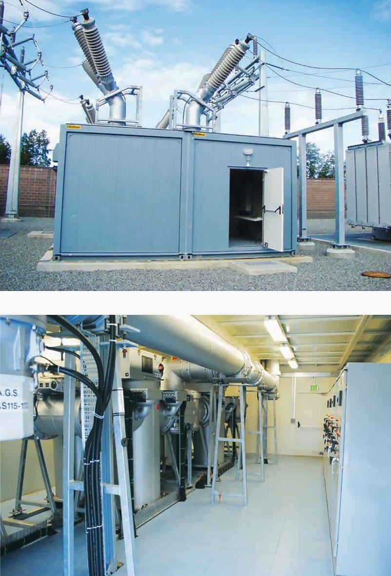
3. Prefabricated, modular transformer substations
The prefabricated, modular transformer substations with gas or air-insulated switchgear are a special design for transformer substations. The individual modules are delivered ready for installation as flexible assemblies. A number of these modules (e.g. medium voltage, control system/control room, auxiliary power etc.) are fully assembled and tested in the factory in prefabricated and transportable housings, every one conforming to the ISO 668 standard dimensions.
The modular principle enables solutions tailor-made to requirements with a high degree of standardization. Prefabricated ISO steel pit modules with the following dimensions are used as transformer bases:
- Up to 16 MVA: 3 pit modules 20 feet x 8 feet
- From 20 to 40 MVA: 3 pit modules 30 feet x 8 feet
- From 63 to 125 MVA: 3 pit modules 40 feet x 8 feet
The pit includes the transformer rails for longitudinal and transverse movement, a flame-suppressant cover and as an option, the required racks for power cables and neutral treatment. Depending on the size of pit selected, space for an auxiliary transformer is also provided. Three pad modules can fit an ISO standard container for shipping.
Modular fire-protection walls are available for fire protection between the transformers and towards the building.
Some advantages of modular transformer substations are:
- Faster construction of infrastructure,
- Shortest possible interruption of power supply in the event of faults and on installation of new equipment and retrofit and service of existing installations,
- Reusable interim solution (temporary solution),
- Stationary, space saving permanent solution, and
- Auxiliary supply in power stations and power station generator busducts
The modular housing design for the MUW consists of hot-galvanized sandwich wall panels for extremely high durability. The steel base frame comprises hot-galvanized rolled steel sections with additional equipment racks. Heating and air-conditioning units in the individual modules allow installation independent of the local climate conditions.
Figures 11 and 12 show the ground plan and the sectional view of a 123/24 kV transformer substation with two 63 MVA transformers and an H-configuration with 5 circuit-breakers on the high-voltage side.
Where,
- High-voltage substation: H-configuration with 5 circuit-breakers,
- Medium-voltage switchgear: 24 bays,
- Neutral treatment (under module 1),
- Auxiliary supply,
- Control system/control room,
- Modular transformer oil pit with 63 MVA transformer, and
- Modular fire protection wall, 9 Personnel module with small sewage system and oil separator
Where,
- High voltage module,
- Medium voltage module,
- Neutral treatment, and
- Foundation modules as cable basement
In addition to transformer substations with gas-insulated switchgear technology, the modular concept can also be implemented with air-insulated components. The modular systems include an outdoor module, which is shown in Figure 13, detail 1, as well as the compact switching modules described above in the first paragraph.
The complete module is prefabricated, tested in the factory and then compactly packed for shipping on the base frame under an ISO container cover. The method of assembly allows direct connections to existing overhead lines without requiring additional gantries with a one-level tower configuration.
Where,
- Outdoor module,
- Transformer module,
- Connection to overhead line, and
- Conventional voltage transformer
Source: ABB
Related electrical guides & articles


Edvard Csanyi
Hi, I'm an electrical engineer, programmer and founder of EEP - Electrical Engineering Portal. I worked twelve years at Schneider Electric in the position of technical support for low- and medium-voltage projects and the design of busbar trunking systems.I'm highly specialized in the design of LV/MV switchgear and low-voltage, high-power busbar trunking (<6300A) in substations, commercial buildings and industry facilities. I'm also a professional in AutoCAD programming.
Profile: Edvard Csanyi

ABB Compass and PASSM0 modules Brochures and catalogues were studied and some of its content was used in my final 5th year dissertation before graduating from Technology University of Lublin in 2006.
The SF6 gas exceptional thermal conductivity and arch quenching and self regeneration properties as well as great dielectric withstand were ground breaking technology in comparison to widely used in Substations above 33kV then air, oil, air blast technologies. This made me chose ‘SF6 filled switchgear and apparatus in Power Systems’ to be the subject of my dissertation.
I really enjoy this kind of article. Thank you very much for your detail explanation with drawings. It’s wonderful. PASS is very applicable to the renovation of existing S/S. Great!
Good job! It’s very helpful!
It is indeed important to know ways to optimize high voltage switchgear in terms of space and cost. And this article really great helps Thank you so much!.