
Estimated Study Time: 21 minutes
Why the need for shunt reactors?
Due to changes in the generation and load structure, the transmission and distribution networks are always encountering new challenges. Many regions, for example, are gradually changing their power networks, such as expanding generation, joining local/regional grids, and moving from overhead lines to high voltage cables for environmental reasons, among other things.
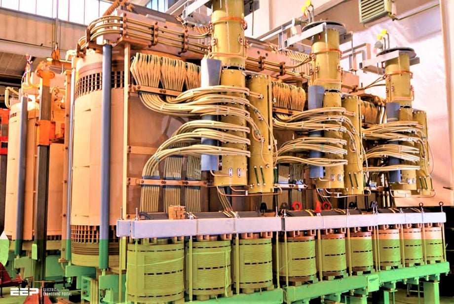 Shunt reactor fundamentals: Connections in the substation, switching and protection practice (on photo: 220kV shunt reactor; credit: ptsco.vn)
Such adjustments are normally done in stages, and they are frequently accompanied by a shift in the demand for reactive power compensation. This is where we come to the subject of this technical article – the essentials of shunt reactors.
Furthermore, the increased usage of renewable energy sources is transforming traditional generation systems and putting new strains on the transmission network. When the system is optimized for energy efficiency as a whole, the dynamic and time-varying effects associated with renewable sources play a more prominent role in networks.
Let’s discuss about the essentials of substation connections, switching and protection:
- Introduction to shunt reactors
- Connections in the substation
- Synchronous switching of shunt reactor circuit-breakers
- Thyristor (phase-angle) controlled reactors (TCR)
- Single, and three-phase reactors
- Relay protection for directly earthed shunt reactors
- Design of high impedance differential protection
- Typical shunt reactor control schemes
- Traditional shunt reactor protection and control schemes
1. Introduction to shunt reactors
Shunt reactors are used in high voltage systems to compensate for the capacitive generation of long overhead lines or extended cable networks. The reasons for using shunt reactors are mainly two. The first reason is to limit the overvoltages and the second reason is to limit the transfer of reactive power in the network.
If the reactive power transfer is minimized i. e. the reactive power is balanced in the different parts of the networks, a higher level of active power can be transferred in the network. Reactors to limit overvoltages are most needed in weak power systems, i.e. when network short-circuit power is relatively low.
Voltage increase in a system due to the capacitive generation is:

where,
- QC – the capacitive input of reactive power to the network, and
- Sshc – the short circuit power of the network.
With increasing short circuit power of the network, the voltage increase will be lower and the need for compensation to limit overvoltages will be less accentuated. Reactors to achieve reactive power balance in the different parts of the network are most needed in heavily loaded networks where new lines cannot be built because of environmental reasons.
Four leg reactors also can be used for the extinction of the secondary arc at single-phase reclosing in long transmission lines. Since there always is a capacitive coupling between phases, this capacitance will give a current keeping the arc burning, a secondary arc.
By adding one single-phase reactor in the neutral the secondary arc can be extinguished and the single-phase auto-reclosing successful.
Suggested video – Where shunt reactors are used
Go back to the Contents Table ↑
2. Connections in the substation
The reactors can be connected to the busbar, a transformer tertiary winding, or directly to the line, with or without a circuit-breaker (see Figure 1).
Tertiary connected reactors will have the lowest cost but extra losses will be obtained in the transformer. The rated voltage of the reactor must be taken into account as well as the large voltage drop at the power transformers. A voltage drop in the tertiary, equal to the power transformer impedance, will be obtained when the reactor is connected.

Let’s assume that the transformer has an impedance voltage of 15% and a rated voltage in the tertiary of 20 kV. Also, assume that the auxiliary power to the station is taken from the tertiary through a 20/0.4 kV transformer.
When a reactor with rated power equal to the rated power of the tertiary winding, is connected, the voltage in the tertiary will decrease to 0.85×20 = 17 kV. This will also mean that the auxiliary power voltage will decrease by 15% and some kind of voltage stabilization regulation is, therefore, necessary to keep the 0.4 kV voltage level within required limits.
Line Reactors can either be connected continuously together with their line or be connected to the network at low load conditions.
Go back to the Contents Table ↑
3. Synchronous switching of shunt reactor circuit-breakers
As we all know, all three-phase systems have a 120 electrical degree phase shift between each phase. A standard circuit breaker switches all three phases at the same time. With controlled switching the phases are independently operated at the most favorable time instant for minimizing electrical transients.
Nowadays, synchronized closing, and opening of shunt reactors CBs, is possible by using a dedicated relay. This will give the closing impulse at the correct instance to achieve pole closing at maximum phase voltages. Closing at voltage maximum gives the minimum possible disturbances in the network.
See Figure 2.

Shunt reactors CBs should be closed at voltage maximum. For example, circuit breakers with ABB’s Switchsync relay to control the closing instance don’t require any pre-insertion resistors, which means a less mechanical complex CB, and of course, a less expensive CB.
Switchsync relay can also be equipped with an adaptive control which automatically will adjust to changes in the CB’s operating time.

This way, by using such synch relay, we can achieve de-energization at optimal arcing time and prevent re-ignitions.
Go back to the Contents Table ↑
4. Thyristor (phase-angle) controlled reactors (TCR)
In order to get continuous control of the reactive power and to damp power swings in the network, thyristor-controlled reactors can be installed. These can respond within only half a cycle delay to the required amount of reactive power needed. The current is controlled in such a way, that the firing pulses to the thyristors are delayed so that they won’t disturb the natural zero crossings of the current.
This regulating can be done continuously and reactive power can therefore be steplessly adjusted to the required value (see Figure 3).

This control is practically transient-free but causes harmonics, that have to be taken care of by harmonic filters. The harmonics generated, are n × f ± 1, where n is an integer. The harmonics of the lowest order are the largest and the level decrease with higher orders. Filters therefore normally only are needed for 5’th and 7’th harmonics.
TCR reactors are always both connected to the network through a power transformer, and delta connected (see Figure 4). The voltage level is chosen to get a current suitable for the rated currents of the thyristors selected.

Go back to the Contents Table ↑
5. Single, and three-phase reactors
Three-phase reactors are manufactured for system voltages up to 400 kV. At higher voltages, the reactors usually are of single-phase type and more or less necessary for the operation of the system. Using single-phase units makes it easier with spares, as only one single-phase unit has to be kept in the substation.
Sizes can either be standardized by the customer or individually optimized for each case.
Suggested Video – Capacitors and reactors explained in detail
Go back to the Contents Table ↑
6. Relay protection for directly earthed shunt reactors
A differential relay, of high impedance type, should be used as main protection. Current transformers (CTs) should be specified at both the phase and the neutral side of each phase and three-phase protection should be used as three-phase protection gives higher sensitivity for internal faults.
If the reactor has its own circuit breaker (CB), the CTs at the phase side could be located together with the CB. If the reactor is connected without CB a bushing CTs should be used. CTs on the neutral side of the winding should be integrated into the reactor (bushing CTs).
If it isn’t possible to get one CT at each phase on the neutral side a common CT at the earth connection must be supplied. In this case, a single-phase high impedance protection should be supplied.
This means that the setting of an included earth fault current protection would in principle be the same as the overcurrent protection and any increase of the sensitivity can not be obtained by earth fault current protection and it is thus not required.
Suggested Course – Overcurrent Protection Course: Principles, Relays, Schematics and Settings
Overcurrent Protection Course: Principles, Relays, Schematics and Settings
Go back to the Contents Table ↑
7. Design of high impedance differential protection
7.1 Relay setting
The general requirement on the function values of the high impedance differential protection is that at maximum through fault current for external faults the relay won’t maloperate even with one CT fully saturated. For a reactor, the dimensioning criteria will be for the inrush current since a reactor only will give a through fault current equal to rated current, at an external earth-fault.
The maximum inrush current for a reactor is approximately two times the rated current. If no specific requirement concerning at what current the relay should be stable exists, five times the rated current is used when the operating voltage is selected.
If there are maloperation problems at the opening of the CB, the remedy for this is to connect a capacitor in the relay circuit. The function value of the relay should be chosen:
Ufunction ≥ 5 In (Rct + Rl)
where,
- In is the reactors rated current at the secondary side of the CT,
- Rct is CT secondary resistance at 75 °C and
- Rl is the lead resistance, from the CT to the summation point.
The principal connection for one phase is shown in Figure 5 below.

In order to protect the shunt reactor from overvoltages at internal faults, non-linear resistors are connected, in parallel with the relay, at each phase (see Figure 5).
Go back to the Contents Table ↑
7.2 Current transformer design
Current transformers (CTs) for High impedance type Differential protection must have a saturation, or knee-point voltage, of at least twice the selected operation value of the relay. CTs must not be equipped with turn correction since this could lead to maloperation of the protection.
If possible the CTs on the phase and neutral side should be made with similar magnetizing characteristic. The ratio of the CTs should be chosen corresponding to approximately twice the rated current. This is done in order to not getting too few secondary turns.
Secondary rated currents should be selected to 1 A, since the primary rated current usually is quite low, and 5 A will give too few secondary turns.
Suggested Reading – The most frequent errors in specifying current transformers (CTs)
The most frequent errors in specifying current transformers (CTs)
Go back to the Contents Table ↑
8. Typical shunt reactor control schemes
The shunt reactors are generally designed for natural cooling with the radiators mounted directly on the tank. However sometimes it is required to have some control action in the cooling circuit depending on the status of the shunt reactor circuit breaker. The control action can be initiated by the circuit breaker auxiliary contact or by operation of an overcurrent relay set to 50% of the reactor rated current.
By using overcurrent relay secure control action is obtained when reactor is energized regardless the circuit breaker auxiliary contact status.
However user must carefully check relay performance regarding the following points:
- Overvoltage and undervoltage relay with reset ratio or 1% or better is required for such application.
- Typically more than one over/under voltage level with independently settable time delays are required within the relay.
- Over/under voltage relay shall be capable to operate only when all three voltages are above/below set operate level or relay must be capable to measure and operate on the value of the positive sequence voltage.
Go back to the Contents Table ↑
9. Traditional shunt reactor protection and control schemes
Usually multifunctional numerical protection relays are used for both power transformer and shunt reactor protection. However, typically old protection schemes for shunt reactor protection, with just a few protection functions are still specified and applied today.
Two such traditional protection arrangements are shown in Figures 6 and 7.
Figure 6 – Typical Shunt Reactor Protection Scheme No.1

The first protection scheme utilizes restricted ground fault protection (i.e. 87N) as reactor units protection. This protection shall trip instantaneously for all internal phase to ground faults. For internal phase-to-phase fault detection, overcurrent protection (i.e. 50/51) is utilized.
Ground overcurrent protection (i.e. 50G/51G) is used as backup protection for ground faults and as main protection for circuit breaker pole disagreement condition.
Figure 7 – Typical Shunt Reactor Protection Scheme No.1

The second protection scheme utilizes differential protection (i.e. 87) as reactor unit protection. This protection shall trip instantaneously for all internal phase to phase and phase to ground faults.
All proposed protection or control functions in Figure 8 are typically readily available in multifunctional numerical transformer protection relays. However suitability of a particular relay to be used for shunt reactor application shall be carefully evaluated.
Figure 8 – Example of complete HV shunt reactor protection and control scheme with multifunctional, numerical relay

Go back to the Contents Table ↑
Sources:
- Protection application book by ABB
- HV shunt reactor secrets for protection engineers by Zoran Gajić, Birger Hillström (ABB Sweden), Fahrudin Mekić (ABB Inc.)
- Variable Shunt Reactors: Applications and System Aspects by C. Bengtsson1, K. Ryen, O.A. Rui, and T. Olsson
Related electrical guides & articles


Edvard Csanyi
Hi, I'm an electrical engineer, programmer and founder of EEP - Electrical Engineering Portal. I worked twelve years at Schneider Electric in the position of technical support for low- and medium-voltage projects and the design of busbar trunking systems.I'm highly specialized in the design of LV/MV switchgear and low-voltage, high-power busbar trunking (<6300A) in substations, commercial buildings and industry facilities. I'm also a professional in AutoCAD programming.
Profile: Edvard Csanyi

I’m from Papua New Guinea 🇵🇬.
I’m working as an Industrial Electrician currently.
I’m interested in this article.
Where do I enroll apply for a study in this field?
If you have multiple transmission line circuits, can all sets of HV shunt reactors be connected to one circuit if all the other circuits are denergized? What would this accomplish if so, further protection to use multiple shunt reactor sets for one circuit?