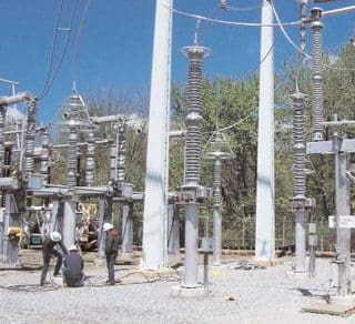
Main Power System parameters are System Voltages and Frequency which normally indicate the healthiness level (they indicate the level of Generated active and reactive Powers against the load power requirement). In a healthy system, Voltage and frequency are close to the rated system values.
Increased active and reactive power load tends to decrease the system frequency and voltage levels respectively. It then becomes essential to generate additional active and reactive power. Synchronous Generators respond to the demand by means of Governor/AVR control systems.
In order to preserve MVA capability of Generators (stator thermal limit) it is preferred to have reactive load support from other sources of reactive power like fixed Capacitor banks or other FACTS .
Due to their inductive nature of the Shunt Reactor, it is used whenever there is need for compensation of capacitive reactance. Power System loads are predominantly inductive in nature and Capacitor banks are used to compensate for the inductive loads. During system light load condition, often voltages increase beyond the normal operating levels and such a condition demands additional inductive loads to maintain system voltage levels within the normal range.
Generators have limited capacity with regard to under and over excitation operation. Typical Generators have rated power factor (pf) of between 0.8 to 0.85 (lead and lag) at rated MVA. At different MVA loading, Synchronous Generators can be operated within its limit of stability, stator/rotor thermal capacity as over and under-excited.
As mentioned above, during light load condition there is risk of system instability due to generated VAr larger than system can absorb. When system VAr generation is higher than the required VAr load, Generators tend to go to under-excitation. Under excitation limit of AVR is used to prevent level of under- excitation below stability limit.
Voltage rise due to increased total system generated VAr is dependent on the source impedance of the system. Source impedances are inductive in nature and weaker system has larger inductive reactance. It is known that inductive reactance and capacitive reactance are opposite in sign.

%ΔV = MVar (Capacitive) / MVA (system short-circuit) x 100
In Figure 1 above, three different Shunt Compensations are shown namely:
- By Line connected Shunt Reactors (Pos. 2)
- Bus connected Shunt Reactors (Pos. 1)
- Shunt Reactor connected on Transformer Tertiary side bus (Pos. 3)
Resource: Unknown


I’m working on a training lesson and would like to be able to explain capacitive reactance and line impedance to entry level students who are being introduced to a simulated bulk electric system
nice site
hi, I have a query. the neutral point of shunt reactor connected in line is earthed through neutral reactor for limiting the fault current. However the bus reactors are solidly earthed (i.e why not through neutral reactor?). why?
Hi, i have one question, we are using 125MVAr shunt reactor in our 400kV 1 & 1/2 breaker scheme, and it got tertiary winding 1.25 MVAr 33kV, 22A rated, now is there any possibility to do the stability test in OFFLINE.
This is great. though, I have few questions:
1. If “When system VAr generation is higher than the required VAr load, Generators tend to go to under-excitation. Under excitation limit of AVR is used to prevent level of under- excitation below stability limit.” then why do we need shunt reactors. Is it for other parts of the system?
2. Are shunt reactors always connected in parallel?. Sometimes when a bus bar is cut they but a shunt reactor between the two sections.
3.Are shunt reactors also used to reduce rush currents?