
Estimated Study Time: 7 minutes
Transmission and distribution
The conductor system by means of which electric power is conveyed from a generating station to the consumer’s premises may, in general, be divided into two distinct parts i.e. transmission system and distribution system.
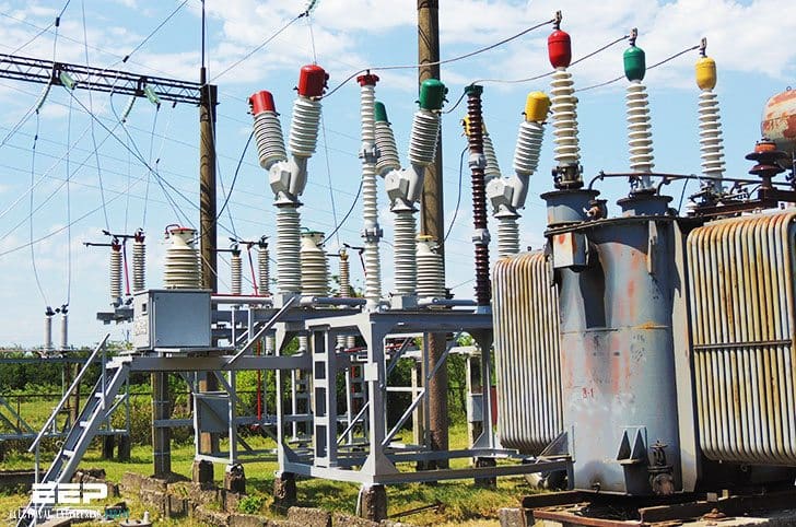 Single-line diagram of the A.C. electrical system (on photo 110kV substation; credit: energo-pro.ge)
Each part can again be sub-divided into two: primary transmission and secondary transmission and similarly, primary distribution and secondary distribution and then finally the system of supply to individual consumers. A typical layout of a generating, transmission and distribution network of a large system would be made up of elements as shown by a single-line diagram of Figure 1 although it has to be realized that one or more of these elements may be missing in any particular system.
For example, in a certain system, there may be no secondary transmission and in another case, when the generating station is nearby, there may be no transmission and the distribution system proper may begin at the generator bus-bars.
Now-a-days, generation and transmission is almost exclusively three-phase. The secondary transmission is also 3-phase whereas the distribution to the ultimate customer may be 3-phase or single- phase depending upon the requirements of the customers.
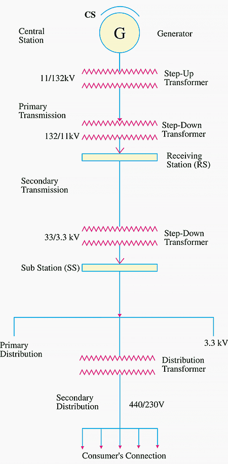
In Figure 1 C.S. represents the central station where power is generated by 3-phase alternators at 6.6kV or 11kV or 13.2kV or even 32 kV. The voltage is then stepped up by suitable 3-phase transformers for transmission purposes.
Taking the generated voltage as 11 kV, the 3-phase transformers step it up to 132 kV as shown. Primary or high-voltage transmission is carried out at 132 kV*.
The transmission voltage is, to a very large extent, determined by economic considerations. High voltage transmission requires conductors of smaller cross-section which results in economy of copper or aluminium. But at the same time cost of insulating the line and other expenses are increased.
Hence, the economical voltage of transmission is that for which the saving in copper or aluminium is not offset by //
- The increased cost of insulating the line,
- The increased size of transmission-line structures and
- The increased size of generating stations and substations.
A rough basis of determining the most economical transmission voltage is to use 650 volt per km of transmission line. For example, if transmission line is 200 km, then the most economical transmission voltage will be 200 × 650 ≅ 132,000 V or 132 kV.
The 3-phase, 3-wire overhead high-voltage transmission line next terminates in step-down transformers in a substation known as Receiving Station (R.S.) which usually lies at the outskirts of a city because it is not safe to bring high-voltage overhead transmission lines into thickly-populated areas. Here, the voltage is stepped down to 33 kV.
It may be noted here that for ensuring continuity of service transmission is always by duplicate lines.
From the Receiving Station, power is next transmitted at 33 kV by underground cables (and occasionally by overhead lines) to various substations (SS) located at various strategic points in the city. This is known as secondary or low-voltage transmission. From now onwards starts the primary and secondary distribution.
The secondary distribution is done at 400/230 V for which purpose voltage is reduced from 3.3 kV to 400 V at the distribution substations. Feeders radiating from distribution substation supply power to distribution networks in their respective areas.
If the distribution network happens to be at a great distance from substation, then they are supplied from the secondaries of distribution transformers which are either pole-mounted or else housed in kiosks at suitable points of the distribution networks.
The most common system for secondary distribution is 400/230-V, 3-phase 4-wire system. The single-phase residential lighting load is connected between any one line and the neutral whereas 3-phase, 400-V motor load is connected across 3-phase lines directly.
It should be noted that low-voltage distribution system is sub-divided into feeders, distributors and service mains.
No consumer is given direct connection from the feeders, instead consumers are connected to distribution network through their service mains. The A.C. distributors are, in many ways, similar to the D.C. distributors as regards their constructional details and restrictions on drops in voltage.
Let’s summarize //
Summarizing the transmission and distribution voltages we have //
- Generating voltage: 6.6, 11, 13.2 or 33 kV.
- High voltage transmission: 220 kV, 132 kV, 66kV.
- High voltage or primary distribution: 3.3, 6.6 kV.
- Low-voltage distribution:
- A.C. 400/230, 3-phase, 4-wire
- D.C. 400/230 ; 3-wire system
The standard frequency for A.C. working is 50 Hz or 60 Hz (as in U.S.A.). For single-phase traction work, frequencies as low as 25 or 16 2/3Hz are also used.
Reference // DC Transmission and Distribution – B.L.Theraja
Related electrical guides & articles


Edvard Csanyi
Hi, I'm an electrical engineer, programmer and founder of EEP - Electrical Engineering Portal. I worked twelve years at Schneider Electric in the position of technical support for low- and medium-voltage projects and the design of busbar trunking systems.I'm highly specialized in the design of LV/MV switchgear and low-voltage, high-power busbar trunking (<6300A) in substations, commercial buildings and industry facilities. I'm also a professional in AutoCAD programming.
Profile: Edvard Csanyi

please release me recent technologies
Like enquire for long distance 22kv distribution lines which sometimes drop voltage alone the way. Is there and solution to install power bank alone the way to boost the voltage capacity. Or is there a possibility to install mini substations say incoming 22kv step up to 33kv and step down again to 22kv…
Please clearify
Would like to seek assistance on 22KV Distribution Construction design and materials.
Hi Edvard,
Interesting articles, lucid and brief. Thanks for the efforts
Hi mr edvard,
quiet interesting reading ur articles, how do one learn to specialize in the system of autocard design. Thanks
Thanks for this elaborate article about the power system. This is so cool :)
Possibly the minimum hydro electric potential that can be tapped globally is three hundred thousand megawatt , from informed sources : comment .
Dear Edwards,
How the reactive power is generated by an alternator I means what causes its generation in alternator ?
I have a doubt when the voltage is stepped up from 11/132 kV again it is stepped down to 11 kV and it is given to receiving station. Is it stepped up to 33 kV at receiving station? If it is done that way please anyone explain the reason. Why can’t we directly step down to 33 kV from 132 kV?
if we convert 133kv to 32kv directly cu loss will be more…for this reason they first step up the voltage…
Dear Abdul Bari,
The Voltage can always be stepped up and stepped down according to the necessity. The standard rating is 132KV/11KV. Say if some industry needs 33 KV for its consumption, the 132 KV line can be stepped down to 33 KV.
At the generation station the generating voltage is upto 15 kv then it is step up to 132kv ,220kv for transmitting to the remote area then again the voltage is step down to 33 kv , 22kv level for distribution system of High tension consumers as per requirements. for the distribution to the residential , commercial nodes it is again step down to 11KV level the again it is step down to 0.433 Kv.
15Kv/132kv-220kv/33kv-22kv/11kv/0.433kv
It is stepped down from 132kV to 33kV. In Nigeria Grid, the 33kV is the secondary transmission that feeds injection substations, where further transformation is done from 33kV to 11kV. The 11kV(s) are the feeders radiating from the substation forming the primary distribution network.
Mr edward plz provide us about switchgear desginig drawings and bus trunking system literature
I would say that nowadays generation is not almost exclusively three-phase, but exclusively three-phase; the same happens with transmission, unless direct current is used.
Also MV distribution is exclusevily three-phase; only LV distribution may be three-phase or single-phase.
The single line diagram should represent generation and EHV and HV transmission with a ring configuration.
MV distribution networks have a “radial” configuration, or although a “double-end feed with NO point” configuration.
LV distribution networks have always a “radial” configuration.
A better accuracy of the concepts would be very usefull for beginers, because this type of articles is irrelevant for profissionals with experience.
I hope that this comment will not be censored.
There are circumstances where HVDC does make sense. –> https://en.m.wikipedia.org/wiki/High-voltage_direct_current
This is absolutely an encouraging lecture which has benefited most of us. So a great appreciation
Thank you Kenneth!
Mr. Edvard,
a pleasant day sir… is it possible that three substation 11kv/400v, 1MVA, share the same cable from a step up transformer of 400v/11kv, 4MVA?