Substation single line diagrams
This technical article describes single line diagrams of two typical power substations 66/11 kV and 11/0.4 kV and their power flow, principles of incoming lines (incomers) and outgoing lines (feeders), busbar arrangement functionality and so on.
Regarding elements in single-line diagrams, they were already explained in previous article, so if you didn’t read it, it’s advisable to do it first.
66/11 kV outdoor substation
Single line diagram
Figure 1 shows the single-line diagram of a typical 66/11 kV substation. Let’s explain the main parts of it and how it actually works.
There are two 66 kV incoming lines marked ‘incoming 1’ and ‘incoming 2’ connected to the bus-bars. Such an arrangement of two incoming lines is called a double circuit. Each incoming line is capable of supplying the rated substation load.
Both these lines can be loaded simultaneously to share the substation load or any one line can be called upon to meet the entire load.
Figure 1 – Typical single line diagram of a 66/11 kV outdoor substation (click to expand)
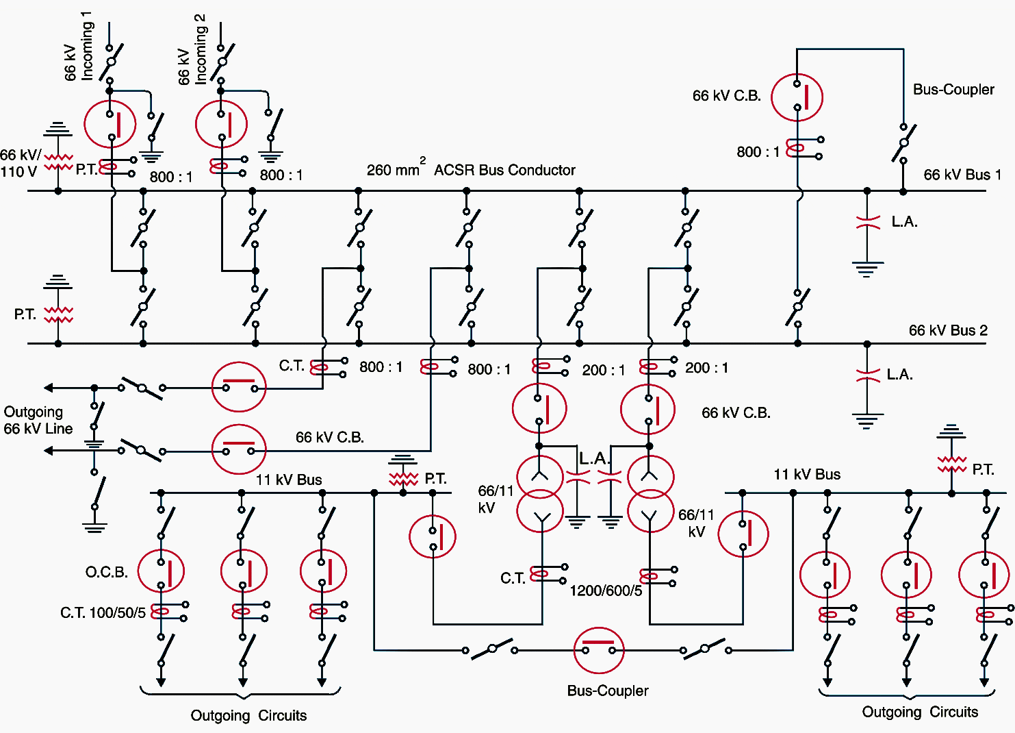

The double circuit arrangement increases the reliability of the system. In case there is a breakdown of one incoming line, the continuity of supply can be maintained by the other line.
The substation has duplicate busbar system: one ‘main busbar’ and the other spare busbar. The incoming lines can be connected to either busbar with the help of a bus-coupler which consists of a circuit breaker and isolators.
The advantage of double busbar system is that if repair is to be carried on one busbar, the supply need not be interrupted as the entire load can be transferred to the other bus.
Generally, one transformer supplies the entire substation load while the other transformer acts as a standby unit. If need arises, both the transformers can be called upon to share the substation load.
The 11 kV outgoing lines feed to the distribution substations located near consumers localities. Both incoming and outgoing lines are connected through circuit breakers having isolators on their either end.
NOTE! Whenever repair is to be carried over the line towers, the line is first switched off and then earthed.
The potential (or voltage) transformers (PTs or VTs) and current transformers (CTs) and suitably located for supply to metering and indicating instruments and relay circuits (not shown in the figure). The PT is connected right on the point where the line is terminated. The CTs are connected at the terminals of each circuit breaker.
The lightning arresters are connected near the transformer terminals (on high voltage side) to protect them from lightning strokes.
There are other auxiliary components in the substation such as capacitor bank for power factor improvement, earth connections, local supply connections, d.c. supply connections etc. However, these have been omitted in the single-line diagram for the sake of simplicity.
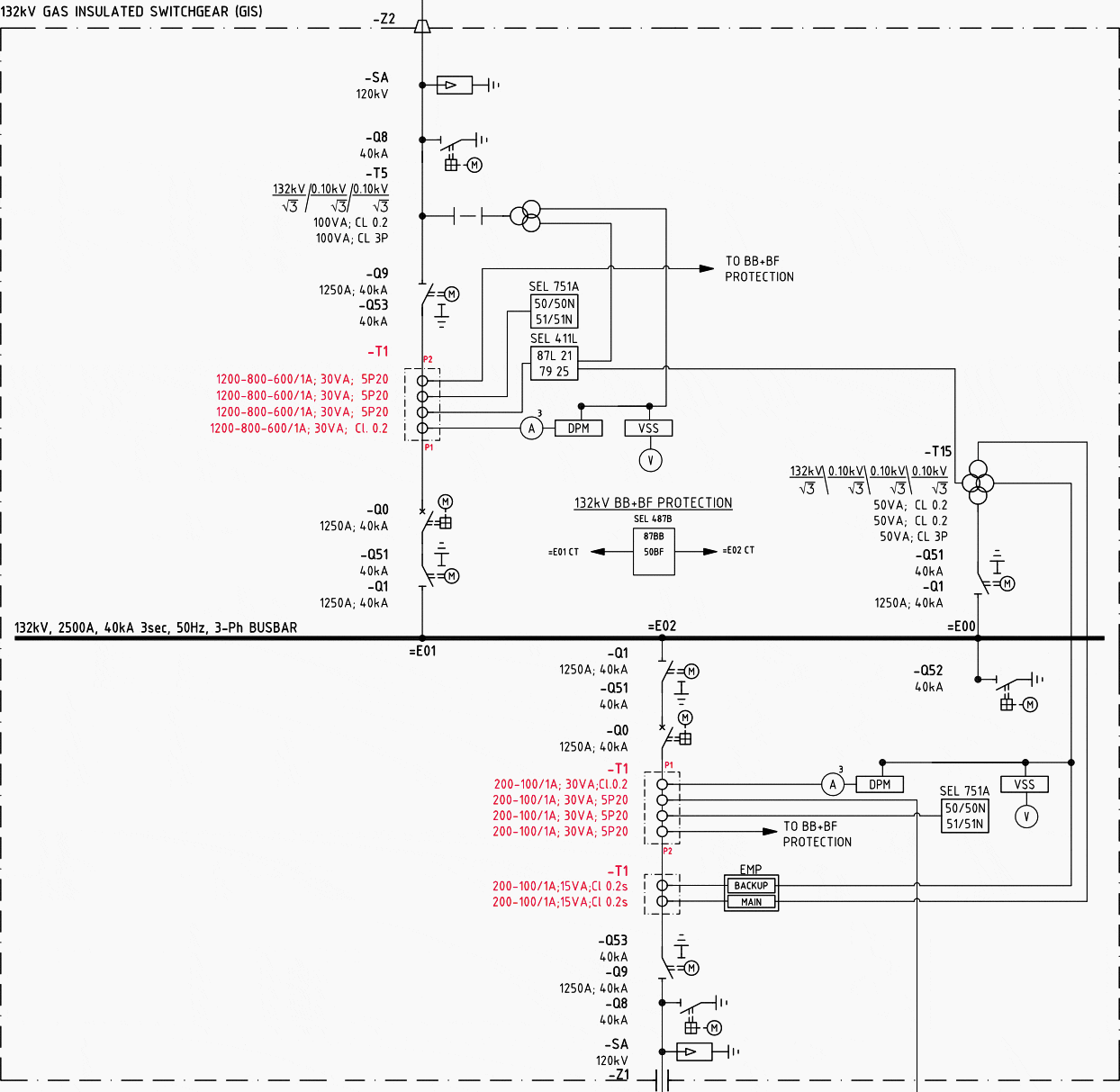
Figure 2 – SLD of GIS switchgear with CTs marked in red

11 kV/400 V indoor substation
Single line diagram
Figure 3 shows the single-line diagram of a typical 11 kV/400 V indoor substation. Let’s explained this scheme a little bit.
The 3-phase, 3-wire 11 kV line is tapped and brought to the gang operating switch installed near the substation. The gang operated switch (G.O. switch) consists of isolators connected in each phase of the 3-phase line. From the G.O. switch, the 11 kV line is brought to the indoor substation as underground cable.
It is fed to the HV side of the transformer (11 kV/400 V) via the 11 kV C.B. The transformer steps down the voltage to 400 V, 3-phase, 4-wire.
Figure 3 – Typical single line diagram of a 11/0.4 kV outdoor substation (click to expand)
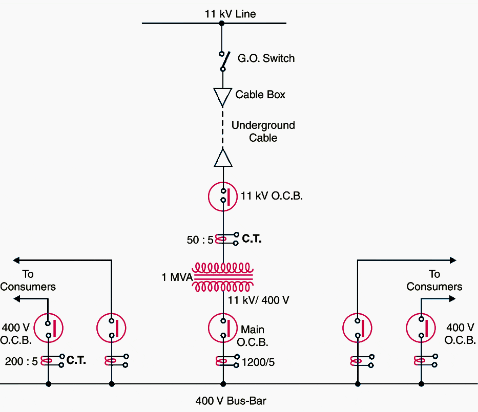

The secondary of transformer supplies to the busbars via the main circuit breaker. From the busbars, 400 V, 3-phase, 4-wire supply is given to the various consumers via 400 V C.B. The voltage between any two phases is 400 V and between any phase and neutral it is 230 V.
The single phase residential load is connected between any one phase and neutral whereas 3-phase, 400 V motor load is connected across 3-phase lines directly.
The CTs are located at suitable places in the substation circuit and supply for the metering and indicating instruments and relay circuits.
Control and Protection System in Substation
Reference: Elements of Power Systems by Pradip Kumar Sadhu and Soumya Das






Hi
A 66/11kV 21m suspension pole is being erected on my garden boundary, approximately 9 metres from my home – I am retired so spend most of the day at home either out or indoors.. I am very very worried not only about the eyesore that this will create for my family but also about the health effects that could result from continuous exposure to the electromagnetic fields from this line and other ones down our road.
Look forward to hearing back from you.
Kind regards
Jos
Which standard did you follow for the symbols used in the single line diagram in this article?
Please can I get the tutorials??
I need material for electrical power installation & design for residential and industrial area. The material shall be step by step. I need explain to my daughter, she is Electrical Engineer just have the graduation information. I graduated in the electrical Engineering in 986. I have the knowledge, but not in a systematic way. Work in project of Telecom and mainly in IPTV site of the Electrical Engineering. I prefer material & information in American standard, but it is not essential
I am kindly requesting for a list of all the materials required to construct an 11kv over head line for a manganese smelter plant from a 66/11kv substation .
Note :
1. 1000kva Transformer to be installed ground mounted (GMT)
2. 5 kilometers of 11kv line from substation
Please giude with a sketch of all the connections on the 66/11kv substation outgoing side and on the ground mounted 1000kv transformer
Hello sir, I would like to know that whether oltc transformerfis required at both levels i.e. from 66kv to 11kv and then from 11kv to 0.4 kV. The incoming line is 66lv and connected load is 15 mva
Pls, send to my mail your available write up on any part of electricity. From 33kva down. And any on Earthing & on electrical maintenance engineer/ work.
They are very meaningful to me.
If we want to represent a three phase wire on SLD how are we supposed to do that?
Does a single line with three strokes represent three phase line?
Yes
Dear sir,
How are you, can you share me, how to design power disteibution LV for 6 power supply 75 Kw and 5 MCC for control pump.
Id like to see a basic line diagram of a primary school because the total kVA calculated seemed to be above 120
Hello sir
Could I know about etap commands , I have to work this but I couldn’t more knowledge it, so kindly help me.
hello sir . how are you
i need to ask you how to design loop system primary distribution system using ETAP or digscilent soft ware
Dear Mr.
I would like to asking you for design MV switchgear access with SCADA using Autocad, EPLAN or another software. Kindly to check it and reply me as soon as possible. Thanks