
Estimated Study Time: 4 minutes
Electric Power System
The principal elements of an electric power system are the generating stations, the transmission lines, the substations, and the distribution networks. The generators produce the electricity, the transmission lines move it to regions where it is consumed, and the substations transform it for industrial, commercial, and residential use.
Finally, the distribution networks carry the electricity to the customers.
Both three-phase and single-phase devices can be powered from a three-phase supply. A three-phase circuit is a combination of three single-phase circuits. The current, voltage, and power relations of balanced three-phase AC circuits can be studied by applying the rules that apply to single-phase circuits.
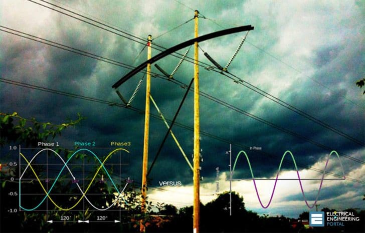
The sine waves of three-phase voltage are separated by 120 electrical degree because they are generated by three separate sets of armature coils in an AC generator. These three sets of coils are mounted 120 electrical degrees apart on the generator’s armature. The coil ends could all be brought out of the generator to form three separate single-phase circuits, but they are conventionally interconnected so that only three or four wires are actually brought out of the generator.
Single-phase AC voltage with zero power factor has both voltage and current sine waves in phase, so they cross the zero line together twice in each cycle.
Similarly, a plot of three-phase voltage sine waves, also with zero power factors as shown in Fig. 1, has all three voltage and current waves crossing the zero line twice each cycle together. Each of its three phases, V1, V2, and V3, is separated by 120 electrical degrees.
Power supplied to each of the three phases of a three-phase circuit also has a sinusoidal waveform, and the total three-phase power supplied to a balanced three-phase circuit remains constant.

Ok, let’s conclude something…
As a result, there are two practical reasons why three-phase power is superior to single-phase power for many applications:
1st reason – Three-phase machines and controls can be smaller, lighter in weight, and more efficient than comparable single-phase equipment. More power is supplied to them in the same period than can be supplied by a single-phase power circuit.
However, the trade-off for this advantage is that three-phase machines and controls are more complex and expensive.
2nd reason – Only about 75 percent as much copper wire is required for distributing three-phase power as is required for distributing the same amount of single-phase power.
Resources: N. Sclater, J. E. Traister – Handbook of electrical design
Related electrical guides & articles


Edvard Csanyi
Hi, I'm an electrical engineer, programmer and founder of EEP - Electrical Engineering Portal. I worked twelve years at Schneider Electric in the position of technical support for low- and medium-voltage projects and the design of busbar trunking systems.I'm highly specialized in the design of LV/MV switchgear and low-voltage, high-power busbar trunking (<6300A) in substations, commercial buildings and industry facilities. I'm also a professional in AutoCAD programming.
Profile: Edvard Csanyi

Why you write 120 electrical degree instead of 120 mechanical degree?
Cmiiw, the value of electrical degree is 180°E only and 360°E or its multiple.
I want to be getting notifications of your released informations or articles.
You can subscribe to our Weekly Digest newsletter:
https://www.subscribepage.com/eep-weekly-digest
There is a powerful power system that feeds railroad in Germany, Switzerland and Northern Europe. It works on the frequency 16 2/3 Hz, single phase, with voltage 2×115 kV in the transmission lines and 15 kV on the trolley conductor.
THe trans use universal series motors very big size.
Dear Engineers,
The main reason why we use 3 phase systems is that the instantaneous power is CONSTANT (I1(t)*U1(t)+I2(t)*U2(t)+I3(t)*U3(t)=const.). That means, when we supply 3 phase motor, the constant power produces constant torque!!! In single phase or two phase systems the instantaneus power IS NOT constant. The smallest number of phases is 3. Of course we can use 4, 5, 6 ect. phase systems ( they have the same feature as 3 phase), but it means more circuit breakers, conductors ect.
Am doing a diploma in biomedical engineering at ECUREI in Mengo Kampala Uganda and am in my first year seeking for a scholarship. thanks
why three phase is preperad over single phase
Please why in a power system supply if you are Using 3 phase supply then neutral phase fail, over current occur but if it’s single phase supply then neutral phase fail low current occur? Why is it this differences
while in distribution feeders i see several houses take single phase supply. but how it is taken with as if several houses doesnt use as much power in other phase causing unequal load? , how the return path carrying return current transfer into three phase nuetral?
hi priyan, just sharing idea here, first of all the unequal load will produce current on neutral wire for 3 phase, recall equation for 3 phase Itotal= I1<0 + I2<120 + I3<120 = 0 for balance 3 phase load "I1 = I2 = I3".
now, answering your question balancing the load for each house so that the resultant current in neutral is difficult, but it can be minimize by controlling the incoming MCB of each house.
example:
if your are going to supply a single phase supply to a 3 house using 3 phase supply 40A 4pole, you have to control the incoming MCB size of each house which is all should be equal. in this case i will take 40A as the MCB, hence, from the equation, no matter how worst the unbalance occur, the worst unbalance current at neutral only limit to 40A only which is save if you size your neutral wire to withstand 100% of the phase current.
reason i use 4 pole mccb in the incoming 3 phase is to limit the current on neutral wire in case of harmonic current.
I have a transformer with a 115 VAC primary and 12 VAC secondary at 1 Amp to power a 4 diode bridge for DC power. If I replace the transformer with a 3 phase unit, what should the current rating of each phase be?
Three phase motors are simpler to operate and control than single phase because single phase motors for high starting torque applications require starting gear (starting relay and/or capacitors) whereas three phase motors do not. AC motors for industrial applications are limited by relay sizing to 5 hp and below. But even below 5 hp, three phase motors are preferred because of the cost and unreliability of starting gear.
“Single-phase AC voltage with zero power factor has both voltage and current sine waves in phase” Don’t you mean UNITI power factor? In phase V-I corresponds to a pf of 1 not 0.. Zero pf corresponds to a +/- 90 deg difference.. Also the 3 main phase coils are separated by 120 physical/spatial/radial degrees not “electrical”.. You cannot separate coils by electrical degrees.. The result, however is 3 phase voltages/currents that have 120 electrical degrees displacement… BTW one of the main advantages of 3-ph power, is it’s natural ability to produce a rotational magnetic field…
*UNITY
why apart from 3-phase multi-phase generation is not available? why not 2,4,5,….?
The more phases used for power distribution, the lower the current rating each single conductor will have to handle, which is good, BUT on the other hand, you’ll need more conductors, meaning more expensive, more complex and more maintenance requirements… So 3<phases = less efficient power system… Multi phase systems are used mostly in electrical machines, where higher mechanical accuracy is required.. but in that case the multi-phase power is locally generated using AC/AC converters..
tell me according to the graph means, in a second Ia,Ib,Ic arent same value ?
eg: Ia=10<0,Ib=10<120,Ic=10<-120
In the industry where i work, 80% of power is used on Motors. It should be noted that 3-phase motors have a high stating torque by design unlike similarly sized single phase motors.
This article is quite useful.