Search

Premium Membership ♕

Save 10% on Pro Membership Plan with coupon DEC10 and study specialized LV/MV/HV technical articles and papers.

Home / Technical Articles / Sizing a Static UPS System In Data Center

UPS system serving a data center

Choosing the power of a static UPS system serving a data center is a decision that involves various elements and which cannot be made before, or independently from, the choice of distribution scheme.
Sizing a Static UPS System In Data Center
Sizing a Static UPS System In Data Center (on photo APC UPS device; by Matthew Landry via Flickr)

The main elements to consider can be summarised as follows:

  1. Two from the following parameters of the loads to be supplied: active power, apparent power or power factor
  2. Type of load power supply (voltage, frequency, number of phases)
  3. Load coincidence factor
  4. Required back-up time
  5. Type of mains power supply (voltage, frequency, number of phases)

Power

The fundamental characteristic of IT equipment loads, and more generally of all loads equipped with switching power supplies, is the current waveform and phase.

Since these power supplies only absorb current close to maximum voltage, the typical waveform, far from being sinusoidal (see Figure 1), has a rather reduced base line and a vertex in correspondence with the voltage peak.

Given the same effective value, this waveform has the peculiarity of having a much higher crest factor than that of a sinusoidal wave.

The static UPS must be able to supply this peak current value, which is normally indicated in the product’s technical specifications as the ‘crest factor‘.
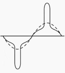
Typical current waveforms of computer loads compared with a sinusoidal wave (dotted line)
Figure 1 – Typical current waveforms of computer loads compared with a sinusoidal wave (dotted line)

In accordance with standard EN 62040-3, the system must not be derated for standardised non-linear loads with a crest factor lower than three (3:1)

Sometimes the nominal power of a static UPS system is confused with terms such as ‘switching power’, ‘computer power’ and ‘actual power’. These expressions were probably coined in an attempt to define a parameter capable of modelling system power even in conditions where the current and voltage waveforms are distorted, nevertheless it should be borne in mind that these parameters do not have an official regulatory definition and therefore cannot have any correlation with the apparent power and nominal active power of the static system.

Consequently, they cannot be used to size a static UPS system.

With regard to the current phase it should be noted thatthe power factor of the loads under consideration is leading, and therefore specific precautions must be taken when sizing the UPS. Current computer loads have input power factors up to 0.9 leading. Note however that there are UPS systems on the market that are able to supply power without derating even this type of load.

If the static system is also required todeliver a large inrush current, as inthe case of lighting fixtures with fluorescent bulbs, this must duly be taken into account.

The parameters are:

  • IUPS – Maximum current value from the UPS
  • tUPS – Time for which IUPS is sustainable
  • Iload – Overload current required by the load
  • tload – Theoretical overload time required by the load

The apparent power required for sizing the UPS will be:

UPS power

Typical values of IUPS and tUPS can range from typical current values of 150% of nominal current for one minute up to 200% per 100 ms without mains power or for UPS systems not equipped with bypass.

The typical cold inrush current of an appliance of the type under consideration is equal to 6 – 8 times the nominal current, and in practice is only limited by the impedance of the UPS and the conductors comprising the part of the distribution network affected by the event.

Autonomy

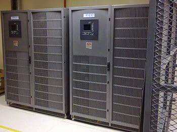
Central Operations Centre – 10 x Apc in row cooling units DX were installed. 3 x 500kVA APC UPS devices
Central Operations Centre – 10 x Apc in row cooling units DX were installed. 3 x 500kVA APC UPS devices (photo credit: dieselelectricservices.co.za)

Autonomy is essentially linked to the time that the data centre is able to guarantee continued operation and if necessary perform a controlled shutdown (typically 30-60 min).

If service must be guaranteed for a long time (roughly 60-90 min), as is often the case, a rotary generator should be provided to supply power to the static system, implementing procedures to ensure fuel replenishment if necessary.


APC UPS Symmetra PX 160 – Overview

Reference: Planning and design for a data center // Electrical Power Infrastructure – EATON

Premium Membership

Get access to premium HV/MV/LV technical articles, electrical engineering guides, research studies and much more! It helps you to shape up your technical skills in your everyday life as an electrical engineer.
More Information
Edvard Csanyi - Author at EEP-Electrical Engineering Portal

Edvard Csanyi

Hi, I'm an electrical engineer, programmer and founder of EEP - Electrical Engineering Portal. I worked twelve years at Schneider Electric in the position of technical support for low- and medium-voltage projects and the design of busbar trunking systems.

I'm highly specialized in the design of LV/MV switchgear and low-voltage, high-power busbar trunking (<6300A) in substations, commercial buildings and industry facilities. I'm also a professional in AutoCAD programming.

Profile: Edvard Csanyi

2 Comments


  1. JANA
    Mar 23, 2016

    sir send me UPS sizing software/excel sheet in my specified mail id


  2. saurabh
    Jan 25, 2015

    Sir I want to design ups system for computer lab. Around 4ppc in lab . can use centralise ups & how to calculate size of ups.

Leave a Comment

Tell us what you're thinking. We care about your opinion! Please keep in mind that comments are moderated and rel="nofollow" is in use. So, please do not use a spammy keyword or a domain as your name, or it will be deleted. Let's have a professional and meaningful conversation instead. Thanks for dropping by!

  −  two  =  4

Learn How to Design Power Systems

Learn to design LV/MV/HV power systems through professional video courses. Lifetime access. Enjoy learning!

EEP Hand-Crafted Video Courses

Check more than a hundred hand-crafted video courses and learn from experienced engineers. Lifetime access included.
Experience matters. Premium membership gives you an opportunity to study specialized technical articles, online video courses, electrical engineering guides, and papers written by experienced electrical engineers.