
Estimated Study Time: 9 minutes
Introduction
Sizing (c.s.a.) and the protection of the neutral conductor, apart from its current-carrying requirement, depend on several factors, namely:
- The type of earthing system, TT, TN, etc.
- The harmonic currents
- The method of protection against indirect contact hazards according to the methods described below
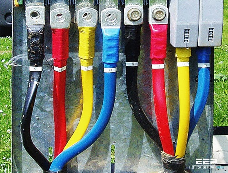
- Green-and-yellow throughout its length with, in addition, light blue markings at the terminations, or
- Light blue throughout its length with, in addition, green-and-yellow markings at the terminations
Sizing the neutral conductor
Influence of the type of earthing system TT and TN-S schemes
Single-phase circuits or those of c.s.a. ≤ 16 mm2 (copper) 25 mm2 (aluminium): the c.s.a. of the neutral conductor must be equal to that of the phases.
- Equal to that of the phase conductors, or
- Smaller, on condition that:
- The current likely to flow through the neutral in normal conditions is less than thepermitted value Iz. The influence of triplen (Harmonics of order 3 and multiple of 3) harmonics must be given particular consideration or
- The neutral conductor is protected against short-circuit, in accordance with the following Sub-clause G-7.2
- The size of the neutral conductor is at least equal to 16 mm2 in copper or 25 mm2 in aluminium
TN-C scheme
The same conditions apply in theory as those mentioned above, but in practice, the neutral conductor must not be open-circuited under any circumstances since it constitutes a PE as well as a neutral conductor (see IEC 60364-5-54 “c.s.a. of PEN conductor” column).
IT scheme
In general, it is not recommended to distribute the neutral conductor, i.e. a 3-phase 3-wire scheme is preferred. When a 3-phase 4-wire installation is necessary, however, the conditions described above for TT and TN-S schemes are applicable.
Influence of harmonic currents
Effects of triplen harmonics
Harmonics are generated by the non-linear loads of the installation (computers, fluorescent lighting, rectifiers, power electronic choppers) and can produce high currents in the Neutral.
In particular triplen harmonics of the three Phases have a tendency to cumulate in the Neutral as:
1. Fundamental currents are out-of-phase by 2π/3 so that their sum is zero
2. On the other hand, triplen harmonics of the three Phases are always positioned in the same manner with respect to their own fundamental, and are in phase with each other (see Figure 1).

Figure 2 shows the load factor of the neutral conductor as a function of the percentage of 3rd harmonic. In practice, this maximum load factor cannot exceed 3.

Reduction factors for harmonic currents in four-core and five-core cables with four cores carrying current
The basic calculation of a cable concerns only cables with three loaded conductors i.e there is no current in the neutral conductor. Because of the third harmonic current, there is a current in the neutral. As a result, this neutral current creates an hot environment for the 3 phase conductors and for this reason, a reduction factor for phase conductors is necessary (see Figure 3 below).
Figure 3Reduction factors for harmonic currents in four-core and five-core cables (according to IEC 60364-5-52)
| Third harmonic content of phase current (%) | Reduction factor | |
| Size selection is based on phase current | Size selection is based on neutral current | |
| 0 – 15 | 1.0 | – |
| 15 – 33 | 0.86 | – |
| 33 – 45 | – | 0.86 |
| > 45 | – | 1 |
Reduction factors, applied to the current-carrying capacity of a cable with three loaded conductors, give the current-carrying capacity of a cable with four loaded conductors, where the current in the fourth conductor is due to harmonics. The reduction factors also take the heating effect of the harmonic current in the phase conductors into account.
Where the cable size selection is based on a neutral current which is not significantly higher than the phase current, it is necessary to reduce the tabulated current carrying capacity for three loaded conductors.
If the neutral current is more than 135% of the phase current and the cable size is selected on the basis of the neutral current then the three phase conductors will not be fully loaded. The reduction in heat generated by the phase conductors offsets the heat generated by the neutral conductor to the extent that it is not necessary to apply any reduction factor to the current carrying capacity for three loaded conductors.
In order to protect cables, the fuse or circuit-breaker has to be sized taking into account the greatest of the values of the line currents (phase or neutral). However, there are special devices (for example the Compact NSX circuit breaker equipped with the OSN tripping unit), that allow the use of a c.s.a. of the phase conductors smaller than the c.s.a. of the neutral conductor.
A big economic gain can thus be made.
Examples
Consider a three-phase circuit with a design load of 37 A to be installed using fourcore PVC insulated cable clipped to a wall, installation method C.
From Figure 4, a 6 mm2 cable with copper conductors has a current-carrying capacity of 40 A and hence is suitable if harmonics are not present in the circuit.
Figure 4 – Clustering coefficient according to the number of current consumers
| Application | Number of current consumers | Ks Coefficient |
| Lighting, Heating | 1 | |
Distribution (engineering | 2…3 | 0.9 |
| 4…5 | 0.8 | |
| 6…9 | 0.7 | |
| 10…40 | 0.6 | |
| 40 and over | 0.5 |
Note : for industrial installations, remember to take account of upgrading of the machine equipment base. As for a switchboard, a 20 % margin is recommended: In ≤ IB x ks x 1.2.
If 20 % third harmonic is present:
Then a reduction factor of 0,86 is applied and the design load becomes: 37/0.86 = 43 A.
For this load a 10 mm2 cable is necessary. In this case, the use of a special protective device (Compact NSX equipped with the OSN trip unit for instance) would allow the use of a 6 mm2 cable for the phases and of 10 mm2 for the neutral.
If 40 % third harmonic is present:
The cable size selection is based on the neutral current which is: 37 x 0,4 x 3 = 44,4 A and a reduction factor of 0,86 is applied, leading to a design load of: 44.4/0.86 = 51.6 A.
For this load a 10 mm2 cable is suitable.
If 50 % third harmonic is present:
The cable size is again selected on the basis of the neutral current, which is: 37 x 0,5 x 3 = 55,5 A .In this case the rating factor is 1 and a 16 mm2 cable is required.
In this case, the use of a special protective device (Compact NSX equipped with the OSN trip for instance) would allow the use of a 6 mm2 cable for the phases and of 10 mm2 for the neutral.
Reference // Electrical Installation Guide 2010 – Schneider Electric
Related electrical guides & articles


Edvard Csanyi
Hi, I'm an electrical engineer, programmer and founder of EEP - Electrical Engineering Portal. I worked twelve years at Schneider Electric in the position of technical support for low- and medium-voltage projects and the design of busbar trunking systems.I'm highly specialized in the design of LV/MV switchgear and low-voltage, high-power busbar trunking (<6300A) in substations, commercial buildings and industry facilities. I'm also a professional in AutoCAD programming.
Profile: Edvard Csanyi

2250kva 415 volt generator neutral conductor size calculation
I work on Offshore Jack-up oil rigs.
I have like you article on EEP.
It gives us good knowledge,and learning never ends.
Thanks
Hi Edvard.
I’m a construction company in South Africa i have 2mva generator in installed on site but itkeeps burning cablesspecial from transformer to change over switch and I’m using 4 core armoured cables as one phase by two per phase at steel plate the current is 2100amps per phase please advise.Thanks regards Bongani.
Hi Edvard
Hope you doing well. I work as a construction company in South Africa I have 2mva generator in installed on site but it keeps burning cables special from the transformer to change over and I using 4 core armoured cables as one phase by two steel glanced about 15 meters distance between the transformer and change over switch thanks regards
I feel so great when I see the page of electrical engineering portal.it’s making me hard working because its course am doing and it was my ambition also my career I was wishing to be.so please keep on doing the great job you doing. Thanks God bless you.
Dear Edward,
Would you please explain how we can identify the percentage value of third harmonic current in a given circuit at the design stage? In other words, is there any practical way of measuring this harmonic current for a given load list ? or we need computer software for calculating this current?
Cheers
It’s crazy to consider and describe computation for “smaller” csa because you can’t use neutral during insulation fault conditions as protective earthing (PEN). I wouldn’t even consider “equal” csa … >>csa. Why limit yourself?
Henry Delforn, EE
In Europe neutral line is blue color in industrial and domestic apllications. In system specifics like locomotives that I work, the neutral is black as the three phases system, only the alphanumeric label indicates the function. In the last ten years the cuttler protection breakers also operates the neutral wire in domestic and industry. In case of simetric loads the neutral wire is one step section size above the phase section.
Dear Edvard
Hope u r fine
I work as an electrical consultant in Jeddah, Saudi Arabia and in the electrical since the last 35 years.
Here, in this part of the world we usually follow IEC / BS specs, although some major big concerns ARAMCO/SABIC/RCJY etc use ANSi / American specs; however the bulk of the work is based on IEC / BS codes.
Having said that; i note that the color coding you have stated in your article for the neutral being blue is a bit astonishing for me here. Following IEC / BS, the neutral specified here is BLACK and not blue.
The three phases being Red, Yellow and Blue.
The grounding/earthing being green/yellow striped. (is PEN mentioned by above the grounding?)
I have not recently read the relevant IEC /BS color coding.
Can you on your part check and advise the correct color coding as per IEC / BS.
Thanks and regards
Anwar Hameed Qureshi
[email protected]
Hi Edvard,
Hope you are doing well. I work for a construction company in Qatar for site temporary Electrical power team leader. Since your are working in schneider can you please describe the advantages of using 4 pole MCCB rather than 3 Pole MCCBS Because in qatar the supply of 4 pole mccb is very less so all the suppliers are asking me to go with 3 pole mccbs.Is it intrinsically Safe to Use ?