
Estimated Study Time: 18 minutes
Introduction to generator CB circuits
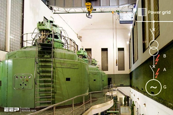
The main function of a circuit breaker is to carry the rated current of the generator and break both the short-circuit current supplied by the generator and that supplied by the power grid. The basic design of the generator circuit configuration is displayed in Figure 1 below. Generator circuit-breakers (GCB) are essentially located between the generator and the step-up transformer of the high voltage network.
 Sizing a MV generator circuit breaker (GCB) in terms of breaking capacity
In generator circuits two different faults are possible with a combination of high short-circuit current at high asymmetrical components:
- The system-source fault (fault on generator side, point A), and
- on system-source fault (fault on the transformer side, point B).
This is in contrast to the values of the short-circuit current under conditions according IEC 62271-100, which is 25 % of the rated short circuit current.
If a system-source fault occurs, the short-circuit current is established at high magnitudes and the breaker is located close to the generator. The energy of the system feeds the fault from the system through the transformer.

Breaking capacity of a GCB
Requirements in terms of breaking capacity depend on the amount the installation contributes to the fault current and the location of the actual fault itself. Figure 1 illustrates a typical single-line diagram and two possible points of failure, i.e.:
- Fault in A – system-source fault
- Fault in B – generator-source fault

Regarding amplitude, fault current supplied by the grid is almost always higher than that supplied by the generator. This is due to the lower reactance of the transformer and network compared to the transient and sub-transient reactance of the generator.
However, when a circuit breaker is chosen for protecting a generator, in accordance with the new Standard IEC/IEEE 62271-37-013 Ed. 1: High-voltage switchgear and controlgear – Part 37-013:
Alternating current generator circuit breakers, short-circuit overcurrent is only one of the parameters required for this specific application. One must also consider the fault in B, supplied by the generator, characterized by higher levels of asymmetry and higher time constants (Figure 2).

Circuit breakers for generators conforming to Standard IEC/IEEE 62271-37-013 are designed to overcome these critical conditions and to withstand longer electric arc duration.
For example, the ABB’s VD4G family of generator circuit breakers includes three apparatuses: VD4G-50, VD4G-40 and VD4G-25 for voltage ratings up to 15 kV, currents up to 4000 A and breaking capacities of up to 50 kA for supply by generator.
Generator circuit breakers must conform to Standard IEC/IEEE 62271-37-013 “High-voltage switchgear and controlgear – Part 37-013: Alternating-current generator circuit breakers”.

The following table lists the breaking capacities of the family in the three conditions:
- System-source,
- Generator-source and
- Out-of-phase conditions.
In the case of generator-source breaking capacity, the first value refers to maximum breaking capacity with 110% asymmetry and the second to 74% breaking capacity but 130% asymmetry (called class G1 in the Standard). The same value means that the circuit breaker is able to interrupt at maximum breaking capacity with 130% asymmetry (called class G2 in the Standard).
If the arcing time resulting from the lack of current zeroes were to exceed the maximum arcing time the circuit breaker is able to sustain, a possible solution would be to delay the release signal of the circuit breaker so as to return below that maximum value.
This would clearly lengthen the time the installation would be exposed to short-circuit current. For that reason, this solution must be carefully assessed and agreed with the user.
The other differences with respect to interruption of faults supplied by the grid are that the rate of rise of the transient recovery voltage (TRV) is much steeper and there are fault currents due to closing in out-of-phase conditions.
Current interruption due to generator-source faults is an extremely complex phenomenon, considering the differences in the way generators behave due to different design and construction techniques.
Since it is very difficult to reproduce these faults in test laboratories, the standard underscores how the only way to assess the capability of a generator circuit breaker to interrupt a short-circuit current with lack of current zero crossing is by simulation.
Example of how a generator circuit breaker is sized
Two generators connected to the HV grid by means of a transformer with three windings are considered in the installation proposed as an example. The starting condition will be that of an initially no-load generator. A 1.05 voltage factor is considered for this installation.
The main grid data are:
- Scc=2000 MVA
- X/R=10
- Vn=150 kV
Transformer with 3 windings:
| V1 = 150 kV | S1 = 150 MVA | Vcc_12 = 11.5% at 55 MVA |
| V2 = 11.5 kV | S2 = 75 MVA | Vcc_13 = 11.1% at 55 MVA |
| V3 = 11.5 kV | S3 = 75 MVA | Vcc_23 = 21% at 55 MVA |
Generators:
- Sn = 75.294 MVA
- Vn = 11.5kV
| Xd = 2.26 | Xq = 2.06 | Td’ = 0.71 | Tq’ = 0.71 |
| Xd’ = 0.217 | Xq’ = 0.26 | Td’’ = 0.04 | Tq’’ = 0.04 |
| Xd’’ = 0.155 | Xq’’ = 0.19 | Ra = 0.001309 |
The reactances and resistances are given in p.u. while the values of the time constants are given in seconds. According to Standard IEC 60034-3, the admissible tolerances can be around ±15 %, thus all reactances are decreased by that percentage as a precaution.
We will first analyze the symmetrical current at instant t=0 (i.e. the moment that short-circuit occurs) on the supply side and then on the load side of the generator circuit breaker (GCB).
We will first consider a three-phase-earth fault between the GCB and generator G1. Application of the MVA method allows the value of the short-circuit symmetrical current to be assessed in just a few steps.
First, we must make sure that the Vcc_12; Vcc_13; Vcc_23 values are given according to the same basis. After this, the values of the short-circuit impedances for each winding can be obtained from the following relations:

Now let us suppose that the transformer with three windings is like the one in the equivalent diagram of Figure 4:

The MVA method can now be applied to the circuit, as shown in Figure 5:

The short-circuit current for a fault between the machine circuit breaker and generator G1 will be calculated first:

The symmetrical short-circuit current at instant t=0 can be obtained from this value.

Ik” is the symmetrical short-circuit current value at time t=0. This value acts as a reference for successive simulation performed via computer using EMTP (Electromagnetic Transient Program) software.
It also allows an initial estimation to be made of the size of the circuit breaker required.
The single-line diagram showing the system-source short-circuit currents for this particular example is given in figure 6 below. Current Isff is the symmetrical short-circuit current to which value Ik” corresponds at time t=0.
The trend of the short-circuit current in the time calculated with EMTP is illustrated in the graph of figure 7.

The graph shows that the maximum current peak is:
Ip = 56.70 kA
while the remaining current values at instant t = 45 ms are:
Issf_sym = 21.38 kA
idc% = 53,75%
Note that the value of the symmetrical component is slightly different from the one observed at instant t=0.
The next data item to assess is the short-circuit current value in the case of a generator-source three-phase to earth fault, considering the symmetrical component at instant t=0 and -15% tolerance on the reactance as explained previously:

Here again, short-circuit current I”kg acts as the reference value for the following computer simulation. The single-line diagram showing the current flow for generator-source faults (Igff) is given below.

The graphs in figures 9 and 10 show the short-circuit current trend for the 90 and 0 degree voltage phase angles, respectively (also calculated with EMTP).

The graph shows that the maximum value of the current peak is:
Ip = 80 kA
Considering a 45ms instant, the remaining current values are as follows:
Isym = 22.52 kA
idc% = 118%
Table 1 – ABB’s generator circuit breaker VD4G family
| System-source breakingcapacity [kA] | Generator-source breaking capacity [kA] | Out-of-phase breaking capacity [kA] | |
| VD4G-50 | 50 | 50/37 | 25 |
| VD4G-40 | 40 | 25/25 | 20 |
| VD4G-25 | 25 | 16/16 | 12.5 |
This result shows that continued operation can be guaranteed by a class G1 circuit breaker, as is for example ABB’s breaker type VD4G-50 (from above table).

Both the graphs in Figures 9 and 10 show the two asymmetry values that must be considered when choosing the circuit breaker, as clearly suggested by the new Standard for generator circuit breakers (IEC/IEEE 62271-37-013 Annex E).
These graphs show that the short-circuit current has a maximum peak value of 80kA and a 22.5 kA symmetrical component.
In the case of system-source faults, thus owing to simultaneous contributions from the grid and generator, the ratio between peak value and the real symmetrical component the instant the contacts separate may exceed the value of 2.74 (standardized value for system-source faults, corresponding to a 133 ms time constant of the direct component).
Checks based on the peak value mentioned above are therefore necessary when assessing the minimum size that can be selected.
The other limit when the MVA method is used for the calculations is that the symmetrical component of the short-circuit current is calculated at instant t=0. However, this value could be useful in the absence of detailed data.
However, to calculate the circuit breaker precisely, the exact characteristic parameters of the generator must be known and the technician who performs the calculation must be fully familiar with the use of EMTP software.
Faults due to out-of-phase must also be assessed if the circuit breaker can be closed in the absence of synchronism between the grid and the generator itself, e.g. owing to faulty operation of the parallelled system.
The fault current that occurs in this case follows the characteristic trend in Figure 11, which mainly depends on the inertia of the rotor and relative turbine connected.

Although it may not seem so frequent, this type of fault must still be considered since its effects can be serious. Thus the capability of a generator circuit breaker to deal with it is of fundamental importance.
Protection relays for generators
All or only some of the following protection functions can be used for protecting the generator, depending on the rated power of the machine and the type of application:
- relay 87 residual current protection of the generator (sometimes called 87G);
- relay 49 thermal overload protection of stator;
- relay 51 overcurrent protection;
- relay 40 loss of field protection;
- relay 32 reverse power;
- relay 46 negative sequence overcurrent protection;
- relay 21 underimpedance protection (as an alternative to zero-sequence overcurrent protection with voltage control when there is a unit transformer);
- relay 50V overcurrent protection with voltage control (as an alternative to underimpedance protection when there is no unit transformer);
- relay 27 undervoltage protection;
- relay 59 overvoltage protection;
- relay 81 underfrequency and overfrequency protection;
- relay 24 maximum overflux protection;
- relay 64R rotor ground protection;
- relay 64S stator ground protection (function of the type of state of the neutral).
There are other protection functions used for high-power machines, e.g.:
- 5 accidental energization;
- 37 underpower relay
- 49R (51R) rotor overload;
- 60 voltage balance relay;
- 78 ou of step.
A few typical protection system configurations are illustrated in Figure 12 as well as an example ABB’s protection relay type REG630 which is recommended in this case.

Generator Protection Fundamentals (VIDEO)
Sources:
- MV switching devices – Technologies & application by ABB
- A three-phase generator vacuum circuit breaker based on vacuum interrupter technology has been established for the application in generator circuits up to 15 kv-50 KA by Dietmar GENTSCH and Stephan SCHOFT (ABB)
Related electrical guides & articles


Edvard Csanyi
Hi, I'm an electrical engineer, programmer and founder of EEP - Electrical Engineering Portal. I worked twelve years at Schneider Electric in the position of technical support for low- and medium-voltage projects and the design of busbar trunking systems.I'm highly specialized in the design of LV/MV switchgear and low-voltage, high-power busbar trunking (<6300A) in substations, commercial buildings and industry facilities. I'm also a professional in AutoCAD programming.
Profile: Edvard Csanyi

I am so Thankful To YOU, for Your Kindness and Generosity to establish Your Very Precious Timeframe in our favour and allowing us to have this very informative, beautiful and admirable presentation.
Thank You Very Much, Sir.
I have always found you electrical engineering articles to be very useful. God bless your kind heart!
Good knowledge
Great useful article. Brief and concise.
Thanks
realy this is fantastic CB. I will use in my design. Rgards
realy this is fantastic CB. I will use in my design. I want full information catalogue and generator set ratings and informatiom. Rgards
MV (15KV) GCB sizing is not clear. Please confirm that 15 KV GCB is sized as per the following rules:
1. Gen. Full load current = 122A (at 13.8KV)
2. GEN. CB Sizing = 130% x 122A = 158.6A
3. Select CB: 200A at 13.8KV
Really, a very useful and informative article on “How to size a MV GCB from viewpoint of breaking capacity”. Thanks a lot, Mr. Edvard and keep it up in future as well please.
Very useful article. Thanks a lot.
Thanks a lot for your effort. With you Dr Abdelaziz Salah Saidi from King khalid university in KSA, college of engineering, power system stability with renewable energy integration
useful and brief , thanks for your effort
VD4G breakers are definitely the best option to protect generator applications.
Thanks for valuable information
This portail is an excellent for all level of electrical engineering. Thanks for this shearing of knowledge.
.
Excellent electric power engineering document.
Thank you.
Dr.- Ing. Robert Josef Taud, DIC ( London)
.
thank u very good work
Thanks
You’re welcome, glad you find article useful.
Very good
thanks