
Estimated Study Time: 15 minutes
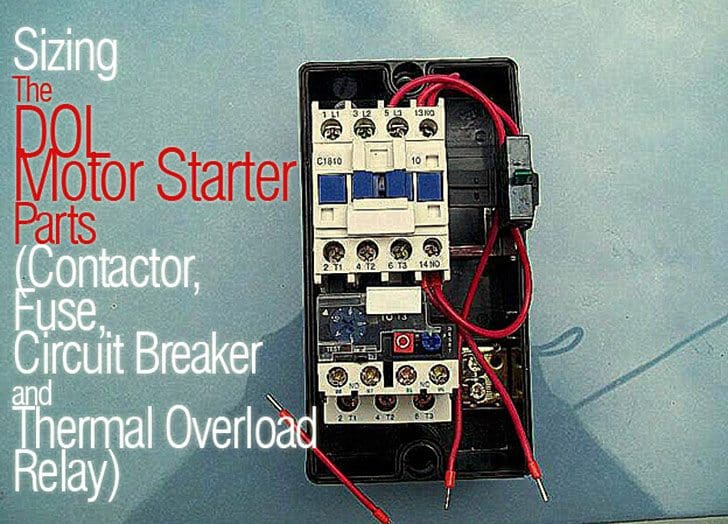
Basic DOL Starter Calculations
In this technical article we’ll calculate the size of each part of DOL motor starter for the system voltage 415V, 5HP three phase household application induction motor, code A, motor efficiency 80%, motor RPM 750, power factor 0.8 and overload relay of starter is put before motor.
Direct-on-line starting is a method of starting a motor that involves connecting it directly to the supply at the rated voltage. This method is referred to by its name. Direct-on-line motor starting, often known as DOL, is an approach that is appropriate for steady supplies as well as shaft systems that are mechanically rigid and well-dimensioned.
Pumps are examples of such systems.
Direct on-line starting of a motor (DOL motor starting) is the most straightforward method, wherein the stator is immediately connected to the mains supply. The motor starts with its inherent characteristics. Upon energization, the motor operates like to a transformer, with its secondary, constituted by the low-resistance rotor cage, in a short-circuit condition.
Despite its benefits (simple devices, higher starting torque, swift start, economical cost), direct on-line starting is only appropriate when:
- the motor’s power is minimal relative to that of the mains, thereby mitigating the impact of inrush current,
- the machine to be driven does not require gradual acceleration or has a damping mechanism to mitigate starting shock,
- the starting torque can be substantial without compromising machine functionality or the driven load.
Basic Calculation of Motor Torque and Current
- Motor Rated Torque (Full Load Torque) = 5252 × HP x RPM
- Motor Rated Torque (Full Load Torque) = 5252 × 5×750 = 35 lb-ft.
- Motor Rated Torque (Full Load Torque) = 9500 × KW × RPM
- Motor Rated Torque (Full Load Torque) = 9500 × (5 × 0.746) × 750 = 47 Nm
- If Motor Capacity is less than 30 KW than Motor Starting Torque is 3× Motor Full Load Current or 2× Motor Full Load Current.
- Motor Starting Torque = 3 × Motor Full Load Current.
- Motor Starting Torque = 3 × 47 = 142Nm.
- Motor Lock Rotor Current = 1000 × HPx figure from below Chart / 1.732 × 415
Locked Rotor Current
| Code | Min. | Max. |
| A | 1 | 3.14 |
| B | 3.15 | 3.54 |
| C | 3.55 | 3.99 |
| D | 4 | 4.49 |
| E | 4.5 | 4.99 |
| F | 5 | 2.59 |
| G | 2.6 | 6.29 |
| H | 6.3 | 7.09 |
| I | 7.1 | 7.99 |
| K | 8 | 8.99 |
| L | 9 | 9.99 |
| M | 10 | 11.19 |
| N | 11.2 | 12.49 |
| P | 12.5 | 13.99 |
| R | 14 | 15.99 |
| S | 16 | 17.99 |
| T | 18 | 19.99 |
| U | 20 | 22.39 |
| V | 22.4 |
- As per above chart Minimum Locked Rotor Current = 1000 × 5 × 1 / 1.732 × 415 = 7 Amp
- Maximum Locked Rotor Current = 1000 × 5 × 3.14 / 1.732 × 415 = 22 Amp.
- Motor Full Load Current (Line) = KW × 1000 / 1.732 × 415
- Motor Full Load Current (Line) = (5 × 0.746) × 1000 / 1.732 × 415 = 6 Amp.
- Motor Full Load Current (Phase) = Motor Full Load Current (Line) / 1.732
- Motor Full Load Current (Phase) = 6 / 1.732 = 4 Amp
- Motor Starting Current = 6 to 7 × Full Load Current.
- Motor Starting Current (Line) = 7 × 6 = 45 Amp
1. Size of Fuse
The purpose of a fuse is to prevent damage to a circuit in the event of a short circuit – very simple and straightforward. The fuse’s design offers protection by rapidly disconnecting the electricity supplied to a system.
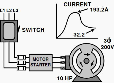
Inductive loads, like squirrel-cage motors, will draw between 6 to 10 times the full-load current upon initial startup. A 200-volt, 10-horsepower motor will use 193.2 amps momentarily before achieving its full-load amperage current (refer to Figure 1). In this instance, it draws six times its full-load current.
Figure 1 – 200 V, 10 HP motor pulls 193.2 A for a short duration before it reaches its full-load amperage current

When this circuit is protected by fuses against short circuits and ground faults (see to Figure 2), the fuse must permit the occurrence of this overcurrent condition without interrupting or disconnecting power to the motor circuit.
Figure 2 – Motor circuit protected with fuses against short circuits and ground faults
Fuse as per NEC 430-52
| Type of Motor | Time Delay Fuse | Non-Time Delay Fuse |
| Single Phase | 300% | 175% |
| 3 Phase | 300% | 175% |
| Synchronous | 300% | 175% |
| Wound Rotor | 150% | 150% |
| Direct Current | 150% | 150% |
- Maximum Size of Time Delay Fuse = 300% × Full Load Line Current.
- Maximum Size of Time Delay Fuse = 300% × 6 = 19 Amp.
- Maximum Size of Non Time Delay Fuse = 1.75% × Full Load Line Current.
- Maximum Size of Non Time Delay Fuse = 1.75% × 6 = 11 Amp.
2. Size of Circuit Breaker
According to NEMA, a circuit breaker is a device that, when used as a disconnect, opens and closes a circuit in a non-automatic manner. A circuit breaker automatically interrupts the circuit due to specified overcurrents resulting from an overload or a short circuit. A circuit breaker triggers a mechanism that disconnects the circuit from the overcurrent state.
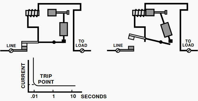
Circuit breakers employ two varieties of tripping mechanisms: a bimetallic or thermal tripping element, and a magnetic tripping element. Circuit breakers sometimes combine both varieties of tripping mechanisms. Such devices can trip instantaneously in an occurrence known as inverse time.
A bimetallic breaker operates with an inverse time characteristic. The current causes the bimetal breaker to flex, resulting in the circuit tripping (see to Figure 3).
Figure 3 – Bimetal breaker makes the circuit trip

A magnetic breaker contains an electromagnet component that activates in response to increased current generated by a short circuit. The activation of a magnetic breaker occurs instantaneously (refer to Figure 4).
Figure 4 – The activation in a magnetic breaker is instantaneous
Circuit Breaker as per NEC 430-52
| Type of Motor | Instantaneous Trip | Inverse Time |
| Single Phase | 800% | 250% |
| 3 Phase | 800% | 250% |
| Synchronous | 800% | 250% |
| Wound Rotor | 800% | 150% |
| Direct Current | 200% | 150% |
- Maximum Size of Instantaneous Trip Circuit Breaker = 800% × Full Load Line Current.
- Maximum Size of Instantaneous Trip Circuit Breaker = 800% × 6 = 52 Amp.
- Maximum Size of Inverse Trip Circuit Breaker = 250% × Full Load Line Current.
- Maximum Size of Inverse Trip Circuit Breaker = 250% × 6 = 16 Amp.
3. Thermal Overload Relay
Overload protection for an electric motor is essential for preventing burnout and to guarantee optimal operational longevity. Whenever there is an overload, a motor will draw an excessive amount of current, which will result in the motor overheating. Motor winding insulation degrades from excessive heat, necessitating defined temperature limitations to prevent the motor from overheating.
Overload relays are utilized in motor control systems to restrict the current consumption.
An overload relay consists of:
- A current sensing unit (connected in the line to the motor).
- A mechanism to break the circuit, either directly or indirectly.
To meet motor protection needs, overload relays have a time delay to allow harmless temporary overloads without breaking the circuit. They also have a trip capability to open the control circuit if mildly dangerous currents (that could result in motor damage) continue over a period of time. All overload relays also have some means of resetting the circuit once the overload is removed.
Figure 5 – Schneider Electric’s Nema magnetic motor starter 240vac coil volts; overload relay with amp setting 45A-135A
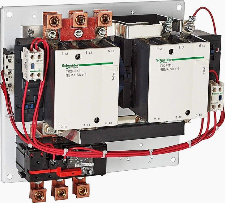
It’s important to epmpasis that the overload relay DOES NOT PROVIDE short circuit protection. The purpose of overcurrent protective devices, such as fuses and circuit breakers, is typically found within the disconnecting switch casing.
Thermal Overload Relay (Phase):
- Min. Thermal Overload Relay setting = 70% × Full Load Current (Phase)
- Min. Thermal Overload Relay setting = 70% × 4 = 3 Amp
- Max. Thermal Overload Relay setting = 120% × Full Load Current (Phase)
- Max. Thermal Overload Relay setting = 120% × 4 = 4 Amp
Thermal Overload Relay (Phase):
- Thermal Overload Relay setting = 100% × Full Load Current (Line).
- Thermal Overload Relay setting = 100% × 6 = 6 Amp
4. Size and Type of Contactor
A contactor, as depicted in Figure 5, would consist of the following parts: an armature, a coil, a spring, an electromagnet (E-frame), and two sets of contacts—one stationary and one moveable.
Figure 6 – Components of the magnetic contactor

What is the mechanism by which the contactor operates to open and close? The E-Frame, once energized by the coil, transforms into an electromagnet. The armature, a part to the E-frame, is connected to a series of contacts. The armature is movable yet restrained by a spring. When the coil is energized, the movable contacts are drawn toward the stationary contacts as the armature is attracted to the E-frame.
Upon the meeting of the two sets of contacts, electrical power can be transmitted through the contactor to the load. Upon de-energization of the coil, the magnetic field dissipates, causing the spring to separate the two sets of contacts.
In summary, contactors work electromechanically, utilizing a minimal control current to open and close the circuit. The electromechanics perform the function, rather than the human hand, as seen in a knife blade switch or a manual controller.
A primary client issue is the lifespan of a contactor. It has been asserted that, “The most harmful action one can take regarding a car is to start its engine.” The same applies to contacts. The greater the frequency of contact openings and closures, the shorter the lifespan of the contactor.
An electrical arc is generated between contacts as they open and close. The arcs generate excess heat, which, if sustained, can harm the contact surfaces.
Contactors are mostly utilized for controlling machinery that employs electric motors. It comprises a coil that is connected to a voltage source. Typically, single-phase motors utilize 230V coils, whereas three-phase motors need 415V coils. The contactor has three primary normally open (NO) contacts and additional lower power-rated contacts referred to as auxiliary contacts (both normally open and normally closed).
These are utilized for the control circuit.
| Application | Contactor | Making Cap |
| Non-Inductive or Slightly Inductive, Resistive Load | AC1 | 1.5 |
| Slip Ring Motor | AC2 | 4 |
| Squirrel Cage Motor | AC3 | 10 |
| Rapid Start / Stop | AC4 | 12 |
| Switching of Electrical Discharge Lamp | AC5a | 3 |
| Switching of Electrical Incandescent Lamp | AC5b | 1.5 |
| Switching of Transformer | AC6a | 12 |
| Switching of Capacitor Bank | AC6b | 12 |
| Slightly Inductive Load in Household or same type load | AC7a | 1.5 |
| Motor Load in Household Application | AC7b | 8 |
| Hermetic refrigerant Compressor Motor with Manual O/L Reset | AC8a | 6 |
| Hermetic refrigerant Compressor Motor with Auto O/L Reset | AC8b | 6 |
| Control of Restive & Solid State Load with opto coupler Isolation | AC12 | 6 |
| Control of Restive Load and Solid State with T/C Isolation | AC13 | 10 |
| Control of Small Electro Magnetic Load ( <72VA) | AC14 | 6 |
| Control of Small Electro Magnetic Load ( >72VA) | AC15 | 10 |
As per above chart:
- Type of Contactor = AC7b
- Size of Main Contactor = 100% × Full Load Current (Line).
- Size of Main Contactor = 100% × 6 = 6 Amp.
- Making/Breaking Capacity of Contactor = Value above Chart × Full Load Current (Line).
- Making/Breaking Capacity of Contactor = 8 × 6 = 52 Amp.
Video Lesson – Simple Motor Start Stop Circuit, Direct Online DOL
Suggested Tool (XLSX) – Calculate Size of DOL and Star-Delta Motor Starter Components
Related electrical guides & articles


Jignesh Parmar
Electrical Middle management professional having more than 22 years rich and dynamic experience in Project Execution / Project Management / Designing / Maintenance diversifies from Electrical Power Transmission (400KV/220KV/66KV)- Distribution(11KV/220V) to Lifts-HVAC-Ventilation-Fire Fighting-Fire Alarm-Lifts-CCTV-Stack Parking Works (High Rise Buildings, Townships, Shopping Complex, Commercial Complex, School, Temple).Profile: Jignesh Parmar

What are the suitable contactor, breaker, and overload for 30hp, 22kw and 42A
refer to IEC standard, what is maximum motor rating on DOL ?
I want to know the right contactors for?
15hp-motor——contactor size
20hp–!!————–!!
30hp–!!————–!!
7.5hp–!!————-!!
Characteristics of Contactors and Starters (IEC 60947-4)
(Modification-1) Shall be AC-4 rated.
(Addition-1) Rated Insulation Voltage shall be a minimum of 660 VAC.
(Modification-2) Shall be rated for uninterrupted duty.
(Addition-2) Rated Operational Current shall be a minimum of 24 A.
(Addition-3) Contactors for motor service shall be selected based upon the
following:
a) On the assumption that all motors operate under 90% AC-3 duty and
10% AC-4 duty
Question:
As per the requirement of the specification ..the contactor Ampere rating for shall be minimum 24A for even for the motor will Less KW loads .
if Coordination is between MPCB,overload and motors there any impact of Contactor if it is oversized?
Current setting of thermal overload relay.
थर्मलर्म ओवर लोड रिले की करंट सैटिंसै गटिं की जाती है।
Option 1 : According to noted current on motor name plate / मोटर नेम प्लेट पर अंकिअं त धारा के अनुसा नु र
Option 2 : On 15% less of supply voltage / सप्लाई वोल्टेज के 15% कम पर
Option 3 : On 10% more of supply voltage / सप्लाई वोल्टेज के 10% अधिक पर
Option 4 : On 10% less load current / भार धारा के 10% कम पर
There is a typographical error in the equation for Max Rated Torque. It should have been 9500 x KW / RPM; 5252 x HP / RPM
Thanks Vinay to inform about the error regarding to writedown the equation
Hello, I am happy with the method or approach, thanks. I am using a 7.5kW motor and it is suitable if I use a contactor and overload relay with a contactor?
Hi, we have a 425hp FCMA starter for motor. We have used Run contactor 1050A where as customer had prescribed for 800A. And start contactor 800 we have used whereas customer needed 500A. Does this create any problem with the product performance. Please suggest.
why hp not watt is being used for drawing Motor lock rotor current?
Dear
first thank you for this website with my wish for more successful, if i have a 92 kw/380v/0.8/184 amp submersible pump and i want to reduce the inrush current how much could reduce the starting current if i use soft starter,
your truly
for induction motor I will use AC7b?
How will you calculate the contactor, Motor Protection circuit breaker, Molded CasecCircuit Breaker, thermal overload and size of power cable and control cable for DOL starter and Star Delta Starter Upto 5 HP & Above 5 HP induction motor. Thank u.
I don’t know how 8×6 becomes 42 in your calculation.
In fact the release shows that 8×6= 52 and not 42, but it also is wrong as well, so some correction or complementary variable and numbers must be added in this equation in order to explain this result.
Which contactor is best suitable for 110kw/150hp slip ring induction motor…stator current196amp/rotor current275amp
8×6=52 How it is possible
Can you please explain . How Motor rated torque value is 35 lb-ft????
How it’s 5252*5*750=35 lb-ft it’s coming 19,695,000 please clarify..
motor rated or full load torque= 5252XHp / RPM
5252*5/750=35 T=5252*HP/RPM
A motor full load current ratting 20 amp .how olr setting formula
20×1.5=30
May you please explain how it is possible to have the Motor Starting Current (Line) = 45 Amp bigger than the
Maximum Locked Rotor Current = 22 Amp?
hi
plz send me 0.5 hp, 1 hp and 10 hp motor slide rules
i think there is something wrong on the value of F max., it should be 5.59 not 2.59 under locked rotor current.
Hi,
I have an EC-DC motor of 0.4 KW. I want to command the motor from a PLC output 24 AC and i want to control the speed of the motor with 0-10 vdc. Could you please guide me for selection of control relay for starting the motor. The motor data is 230 VAC 50Hz single phase.
Also can i use control relay for commanding the motor On and Off.
The page before was better because it allowed copying or downloading what I published in PDF now and only lets print it bad that bad serivicio. I was better before.
Where can I find the required magnetic contactor size for a motor given the motor current or HP?
Hi,
I need tips on how to do sizing of UPS & Automatic Power Factor Correction
We are going to manu.. 2HP single phase monoset pump for agriculture purpose.240V & max curretnt 11.5A. difficulty is i am not getting that how much degree of thermal fuse we can use?
Mr.shafqat
I have a question for you.
I have a two speed motor having twelve(12) input terminals.when we provide supply on twelve terminals what happend???????
Pls I want to know why you chose motor starting torque to be 3x full load current. Thanks
Dear Gents
Please support me to select fuse size for 3 phase motor with LRA 11.4 A V=400, inpout power 1.21Kw, current = 2.3A and how to calculat it?, fause PH (3N)
how we select aa magnetic contactor wth respect to motor
Dear Sir/Mam ,
I have completed bachelor’s degree in Electrical & Electronics engineering branch in 2014 . I have 6months experience in designing electrical panels ( APFC, MCC & PCC panels)& switchgears and software skills in electrical autocad.
Can you please suggest doing PLC, SCADA automation course will hike up my career or not
to get a higher package. If yes please do suggest Institutes for the same
Regards
Sanjul
The starting current is 45A , maximum size of none time delay fuse is 11A ,
Why it will not blow?
Why Code F minimum locked rotor current =5A , maximum locked rotor current =2.59A
Motor starting torque=3 times of motor full load torque or current
3 times or 2 times it is very big difference
i want to know how many torque of 15 kw motor
How will you calculate the contactor, circuit breaker, thermal overload and size of power cable and control cable for DOL starter when u are give a 3KW induction motor. Thank u.
what are the basis for above calculations?
What is the basis of above calculation….
Provide International Standard for Calculation….
Thank you
1.Can we say what is the no load current for a motor if it’s full load current,voltage,power ,power factor are known
5252x5x750 = 35 lb-ft. ????
9500x(5×0.746)x750 = 47 Nm ???????
It should be:
5252×5/750 = 35 lb-ft.
9500x(5×0.746)/750 = 47 Nm
Yes u r right
From where you got multiplying factor, Is there any std/ ref in IS, IEC.etc.
Motor Full Load Current (Line) = KWx1000/1.732×415
Why the power factor is not included in the calculation although it has been give in the details?
p.f is taken in the calculation, but it is missing in the formula
great sir,can u describe about selection of transformer according to connected load, necessary erection steps for transformer erection