
Abstract
Modular Switchboards are used for electrical power distribution in industrial and commercial locations. It is often important to know the dimensions of the Switchboards beforehand, especially in case of large installations like a Power Plant.
 An algorithmic approach to space optimized design of modular switchboards
The details are used for planning the dimension and floor layout of the building where the Switchboards are supposed to be erected, and estimating space for temporary storage of these materials at site location.
Similarly, prior knowledge of weight of the Switchboards is important for estimating commercial aspects like cost of transportation, handling, insurance and erection.
In order to estimate these dimensions, very often simplistic approximations are applied. Several nuances of the design are thus ignored (due to lack of time or to avoid increased complexity), leading to under/overestimated results.
Contents:
- The modular switchboards
- Need for a space-optimized design
- Overview of design (salient design features)
- Problem statement
- Solution
- Sample input
- Parameters
The modular switchboards
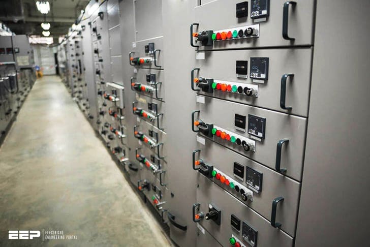
Electrical switchboards that are designed for handling large power are specifically referred to as Metal-Enclosed Switchboards. They are called so as they are made of closed metallic compartments, typically in the form of an array of several vertical panels.
In many Medium and Low Voltage Switchboards, each of the vertical panels comprises of several smaller sub-compartments called Modules. However, a module may also occupy the full length of a panel, as in case of large breaker feeders, found in MV and HV Switchboards.
Modular design of Switchboards allows them to be operated and serviced independently – without affecting the operation of other modules. This is of significant importance from operation and maintenance point of view and is the preferred industrial standard.
Need for a space-optimized design
It is important to understand the need for optimally designing any switchboard before proceeding with doing the same. Typically Switchboards are erected in enclosed spaces which may house other equipments too.
As the room dimensions are fixed, it becomes important to minimize the space occupied by the switchboards, so that they can be placed in the room easily. This case becomes an even greater concern when switchboards have to be placed in already existing rooms that are partly occupied.
Often, the Switchboards are placed on first or higher floor of a building and have bottom entry cables. Thus, floor cutouts have to be made in advance to terminate the cable connecting the load at the switchboard end.
Since, civil activities like sizing a building, determining the strength of foundation, thickness of floors and dimensions of floor cutouts are done much before the switchboard is actually manufactured, hence, it becomes imperative to know the size and weight details of the switchboards beforehand.
Weight being proportional to the size, is also reduced. This has cascading effects as; lower weight implies lower transportation cost, lower freight insurance and handling charges and lower cost of erection.
Switchboards are passive devices and dissipate considerable amount of heat. Once the switchboards are designed, it becomes possible be determine the rate of heat generation. This data is useful for planning the air conditioning and ventilation systems.
It is now clear that the goal of optimality is to reduce the switchboard size. However, this process is governed by numerous design constraints. The problem statement and solution are discussed next.
Overview of design
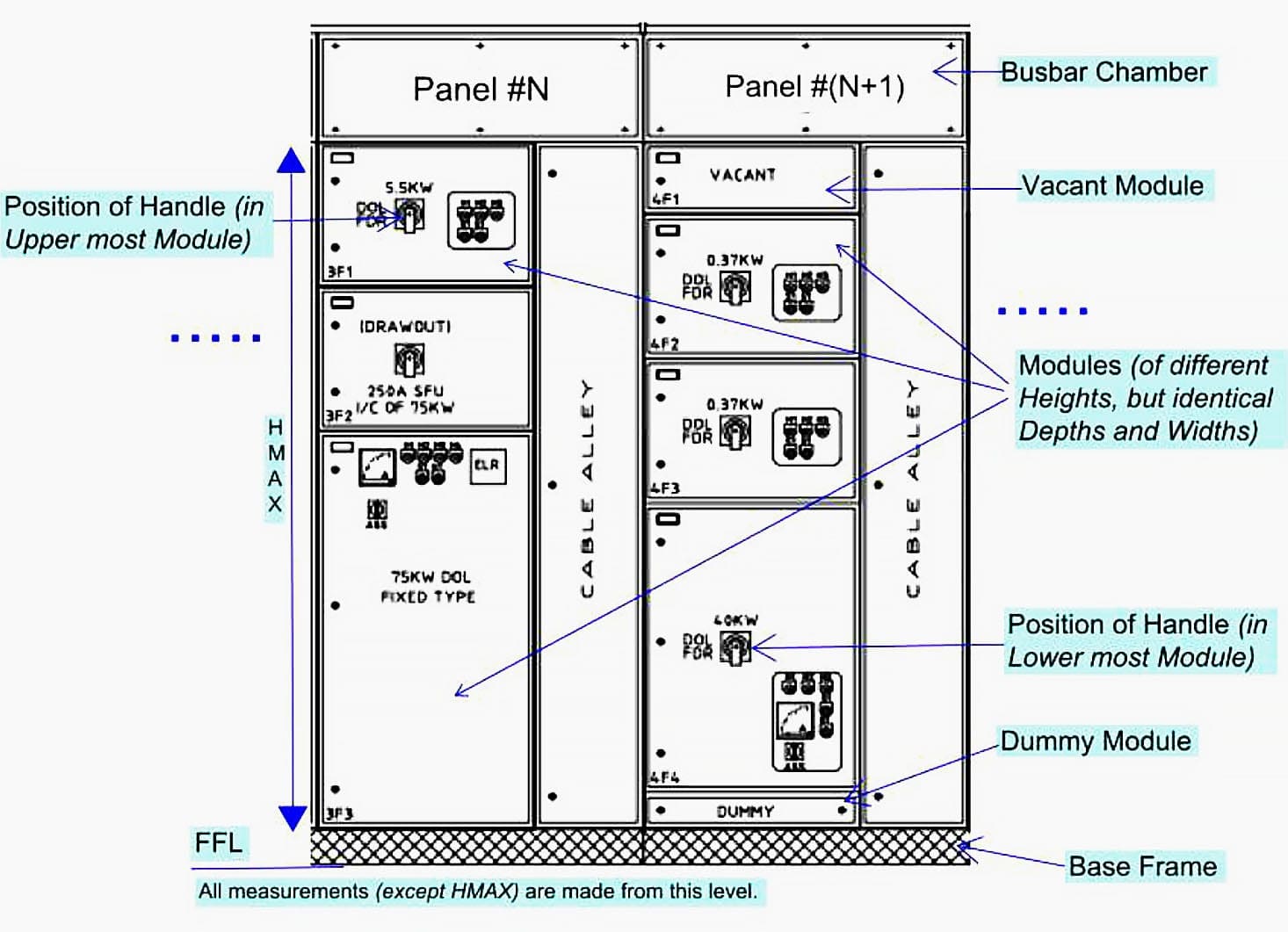
As shown in Figure 1, a modular switchboard consists of several feeder modules stacked together in each vertical panel. The Switchboard, itself is an array of several such panels.
Some of the salient design features are explained below:
Feature #1 – Front and Rear side
Every Switchboard has two sides – Front and Rear. A Switchboard with Single Front (SF) Design will have modules only on the front side of each panel, while those with Double Front (DF) Design have modules on both the front and the rear.
The depth of DF is obviously, more than that of SF Type, but for same number of modules DF will have smaller width than SF.
Feature #2 – Three horizontal sections
Each Panel has essentially three horizontal sections. The bottom most is the Base Frame – a steel section that bears the weight of the switchboard. It is followed by a region where the modules are stacked.
Feature #3 – Handle to close/open the module door
Each module of provided with a handle to close/open the module door. There are often constraints on the height at which the handles of the lower most and upper most modules must appear for ease of accessibility.
Feature #4 – Dummy module
In cases where the lower limit of handle position is violated, a Dummy Module may be inserted to raise the overall height of the handle and meet the constraint.
Feature #5 – Vacant module
Again, it may not be possible to fully utilize the total available height of a panel due to various constraints while stacking the modules. In such cases, the space left shall be marked as a Vacant Module.
Feature #6 – Limit on the max. number of modules
In certain cases, there may be a limit on the maximum number of modules that can be stacked in each panel. Though this constraint does not always give the best compact design, yet it is occasionally encountered.
Feature #7 – Air Circuit Breakers (ACBs)
Air Circuit Breakers (ACBs) are the highest rated switchgear on LV and MV Boards. They occupy significant space and come with certain design constraints, such as:
- Even if two ACBs can be placed in one panel, the design rules may inhibit the same. Such an arrangement is called a Single Tier Design. When up to two ACBs are allowed per panel, the design is called as Double Tier
Design. - The ACBs have special arrangement on their rear sides to allow for Bus Bar interconnection. Because of this the Rear Side of any ACB Panel cannot be used to stack another module, even if the Design is “DF” Type. Thus, the Rear Side of any ACB Panel will always be empty (of modules).
Feature #8 – Cable Alley
Cable Alley is a section of the panel, where power and control cables arise (from bottom) and connect to each module. These alleys need not be part of every panel.
However, from the algorithmic perspective (which follows next), presence or absence of the alleys will not impact the design, since the stacking method is function of module height alone.
Problem statement
Given
The designer is provided with a list of loads that have been considered on a switchboard. These loads have already been distributed on each of the Bus Sections of the Switchboard in accordance with the system operation and design philosophies.
Hence, the height of modules is mentioned against each item in the list. Special components that are part of the Switchboard, but not any feeder in particular (such as Control Transformers, Sub-Distribution Transformers, Bus PTs, Marshalling Terminal Blocks, etc.) are also provided.
Aim
Arrange the modules into different vertical panels, in a manner that results in the most compact design.
Constraints:
- The Switchboard Design Type may be Single Front (SF) or Double Front (DF).
- The Rear End of the Switchboard may be filled with modules only in case of a DF Design.
- The Maximum Usable Height of each Panel is uniform.
- The Height of Operating Handle of the lower most modules shall be maintained above a certain minimum level from the ground.
- The Height of Operating Handle of the upper most modules shall be maintained below a certain maximum level from the ground.
- The Number of Modules per Vertical Panel may be limited to a certain value.
- The Switchboard may have Double Tier (DT) or Single Tier (ST) Arrangement for ACBs.
- All ACB modules shall be located at the Front End of the Switchboard alone.
- The Rear End of any Panel having a DF Design with an ACB module shall be Vacant.
- The Bus Distribution of items in the Feeder List cannot be changed.
Solution
Explaining the idea:
Each item in the Feeder List is fed from its own module. Each module is akin to a box and all the boxes have fixed Depth and Width, but their heights vary. The height of each module depends on the rating and protection type of the load and is specified for each item in the List.
Before beginning the solution, a different case may be studied first. Consider a jar that has to be filled with large pieces of rock, small pebbles and fine sand.
The aim here is to fill in the maximum amount of each of these quantities, which are available in unlimited supply, in to the jar. The constraint here is that the volume of jar is finite and fixed.
In order to solve this case, the natural sequence of filling the jar would be – rocks first, pebbles next and sand last. The smaller items will fill the gaps left between the larger ones.
The stacking of boxes (or modules) in the fixed volume of panels is analogous to the previous case. Here, the first step toward minimizing the number of panels is to proceed by stacking the large modules first.
The process is repeated iteratively. During each iteration all the panels from #1 up to the last one created, shall be checked since any of these may contain vacant space where the current module may fit in.
The algorithm presented below uses this idea in several loops to estimate the optimum size for the given data.
Input:
The input to the algorithm is the data in form of Table-1. Although the input is randomly ordered in the table, it is sorted in descending order by module height before the algorithm accesses it.
Process
Table-1 shows that each module can have multiple units which are distributed on one or more bus sections. The algorithm processes one bus section at a time. During each iterative loop, all units of a given module for current bus are stacked into the panels.
A flag is used to indicate successful stacking of each unit.
Programmatic implementation
The algorithm works essentially by using the input parameters as constants and Module and Panel attributes as variables. These attributes closely follow the object model of OOPS.
Thus, both the Panel and Module are treated as class objects, with the following properties.
For Panel:
- Height available on Front Side [HavlF]
- Height available on Rear Side [HavlR]
- Number of modules stacked on the Front Side [ModCountF]
- Number of modules stacked on the Front Side [ModCountR]
- Description of the Front Side arrangement of modules [DescF]
- Description of the Rear Side arrangement of modules [DescR]
- (Flag) Panel contains ACB module [ACBPanel]
For Module:
- Description of each module, such as load name or ID or Tag [Description]
- Type (Protection Element – like SFU, MCCB, ACB, etc. or Component Description – like Bus PT, Marshalling Terminal Block, Auxiliary Transformer, etc.) of each module [Type]
- Number of units of the module [Units]
Of course, non-object type implementation is also possible, but that would be more tedious.
Table 1 – Constants (to be specified for each Switchboard)
| Constant | Typical Value | Description |
| BUS_MAX | 2 | Range may vary from [1, n] (n is generally <= 3) |
| SBD_DGN | DF | Possible values {SF, DF} |
| ACB_DT | True | Possible values {True, False} |
| BFH | 50 | Base Frame Height (measured from FFL in mm) |
| HMAX | 2100 | Maximum Operating Height of each Panel (measured in mm – does not include Base Frame Height) |
| HHL | 300 | Position of Handle on the Lowermost Module (measured in mm from FFL) |
| HHU | 1800 | Position of Handle on the Uppermost Module (measured in mm from FFL) |
| RPHL | 0.5 | Relative Position of Handle on the Lowermost Module (measured from Bottom of Module and expressed on a scale of [0.0, 1.0]) |
| RPHU | 0.5 | Relative Position of Handle on the Uppermost Module (measured from Bottom of Module and expressed on a scale of [0.0, 1.0]) |
| MMX | 99 | Maximum number of modules to be stacked into each panel. (Note: Any value >10 would imply that there is no limitation.) |
Notes:
- Segments-A and B are almost identical. While Segment-A can insert modules only into the Front Part of the Panel, Segment-B can do the same only on the Rear Part. Segment-B therefore, is executed only when Switchboard has a Double Front Design.
- Going to Stack_Module Label will cause the algorithm to re-test all the PMAX-1 Panels. To speed up the process, Segment-A and B can be copied at this point again (outside the loops) after setting p = PMAX and finally terminating the segment with Goto Next_Module Label.
- When implemented in code, the programming language of choice may not allow the limits of the for-next loop to be changed dynamically during the runtime. This, difficulty may be done away with by implementing the logic using do-while loop construct.
Sample input
Parameters
Output (for Bus-A shown here):


Super
Very interesting article, indeed.
Even if it is applicable basically to MCC (Motor Control Centers, either fixed or plug-in type), with some resctriction, it can be used also for PC (Power Centers or Main Electrical boards), where some “large” loads shall be positioned by hand, as thermal dissipation is an important factor..
Pl. Details provided Automatic phase sequence panel
I am a Professional Electrical Engineer in the Philippines and had good experienced in Design, Construction, Commissioning and Maintenance of all Mining Electrical Equipment and Power Plant operation. I’d like calculation supporting to the event of actual results specially in relay setting and protection system of the Substation Transformer, Transmission line and Distribution system.