Residual current devices (RCDs)
Normally residual current devices (RCDs) are used for protection against direct and indirect contacts. An RCD can detect low leakage currents that could flow through the body of a person. It thus provides additional protection if the normal protection means fail, e.g. old or damaged insulation, human error, etc.
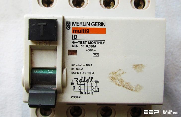
This can also be referred to as ultimate protection because it can interrupt the current even if the other devices have failed.
An RCD is the only solution to protect against indirect contacts on a TT system because the dangerous fault current is too low to be detected by overcurrent protective devices. It is also a simple solution for the TN-S and IT systems.
Let’s take a look at the special applications where RCDs are used and where special attention should be taken.
- When using two and more RCDs – Discrimination
- RCDs connection upstream or downstream of surge arresters
- When leakage currents disturb RCD operation
- Combinations of RCDs and variable speed drives
- Installation with backup sources like Uninterruptible Power Supplies (UPS)
1. Discrimination
The goal of discrimination and protection coordination is to ensure that only the faulty part of a circuit is de-energised by tripping of the protective device.
1.1 Vertical discrimination
This type of discrimination concerns the operation of two protective devices installed in series on a circuit (see Fig. 1).
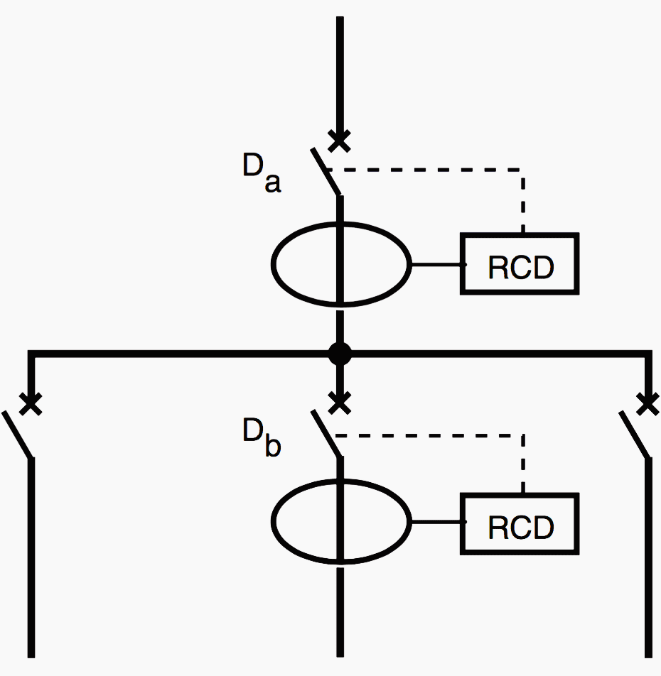

Given the tolerances around the RCD thresholds and break times, both current and time discrimination are used:
Current discrimination because, according to standards, an RCD must operate for a fault current between I∆n/2 and I∆n. In fact, a factor of 3 is required between the settings of two RCDs to avoid simultaneous operation of the two devices, i.e. I∆n (upstream) > 3 I∆n (downstream).
Time discrimination for cases where the fault current suddenly exceeds both rated operating currents (see Figure 2). It is necessary to take into account the response time, even minimal, of all mechanisms, to which it may be necessary to add deliberate time delays.
I∆n (Da) > 3 I∆n (Db) and tr (Da) > tr (Db) + tc (Db) or tr (Da) > tf (Db)
where:
- tr – non-actuating time
- tc – disconnection time between the instant the operating order is given by the measurement relay to the instant of disconnection (including the arcing time),
- tf – break time, from detection of the fault through to complete interruption of the fault current; tf = tr + tc.
The threshold detection circuits of electronic relays may exhibit a fault memorisation phenomenon. It is therefore necessary to take into account a “memory time“, that can be thought of as a virtual increase in the time that a current flows, to ensure that they do not operate after opening of the downstream device.


Note:
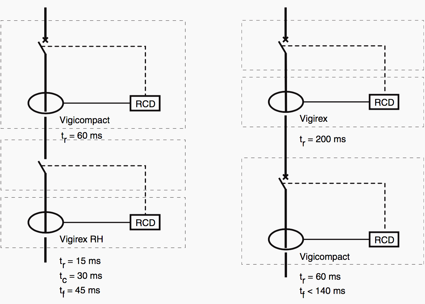
Particular attention must be paid when determining discrimination conditions for circuit-breakers with add-on RCDs and residual-current relays used together (see Figure 3). This is because:
- a circuit breaker with an add-on RCD is defined in terms of the non-actuating time (tr),
- a residual-current relay is defined in terms of the time between the instant the fault occurs and transmission of the opening order, to which it is necessary to add the response time of the breaking device.
It is therefore necessary to calculate the successive tf and tr times (at 2 I∆n, the conventional current for the non-operating test of delayed RCDs) for each RCD, from downstream to upstream.

1.2 Horizontal discrimination
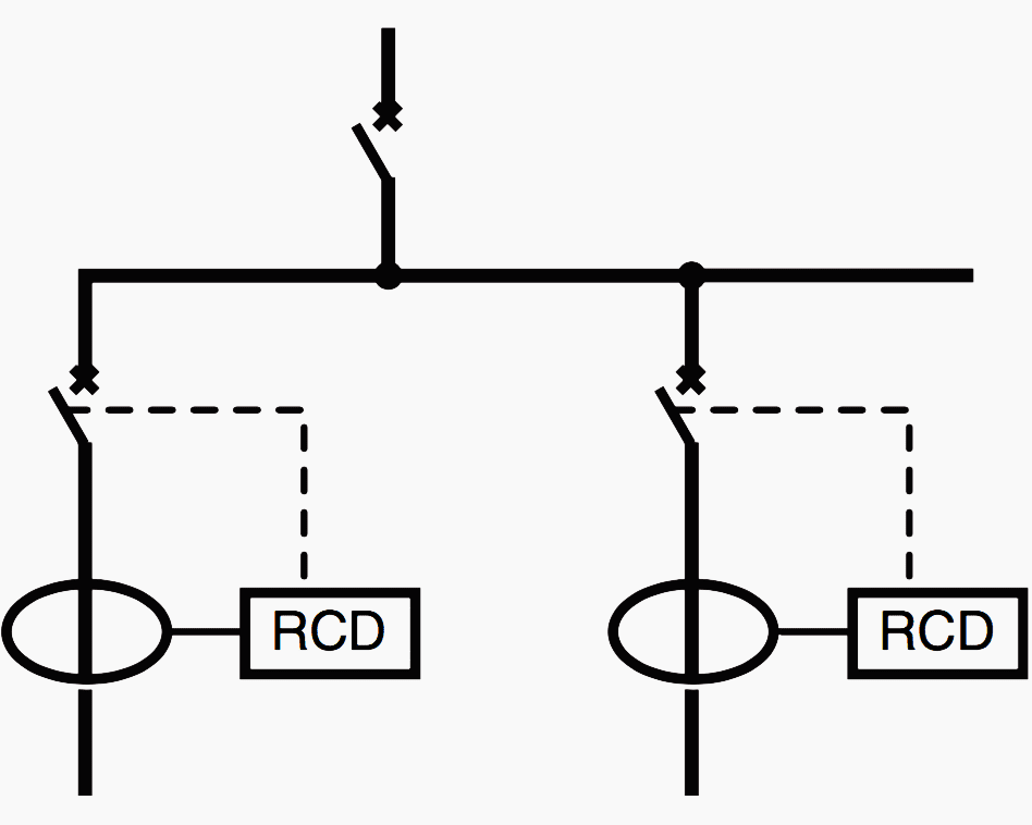
Sometimes referred to as circuit selection, stipulated in standard NFC15-100, section 535.4.2, it means that an RCD is not necessary in a switchboard at the head of the installation when all the outgoing circuits are protected by RCDs. Only the faulty circuit is de-energized.
The RCDs placed on the other circuits (parallel to the faulty one) do not detect the fault current (see Figure 4). The RCDs may therefore have the same tr setting.

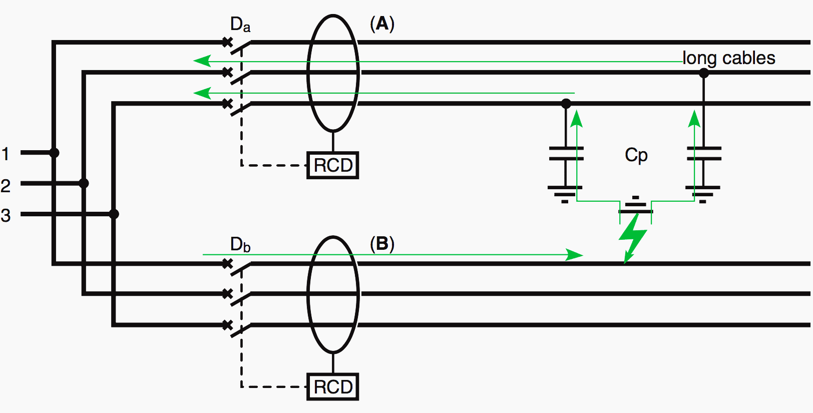
In practice, horizontal discrimination may present a problem. Nuisance tripping has been observed, particularly on IT systems and with very long cables (stray capacitance in cables) or capacitive filters (computers, electronic systems, etc.).
Tripping may occur on non-faulty circuits, as shown in Figure 5.

2. Surge arresters
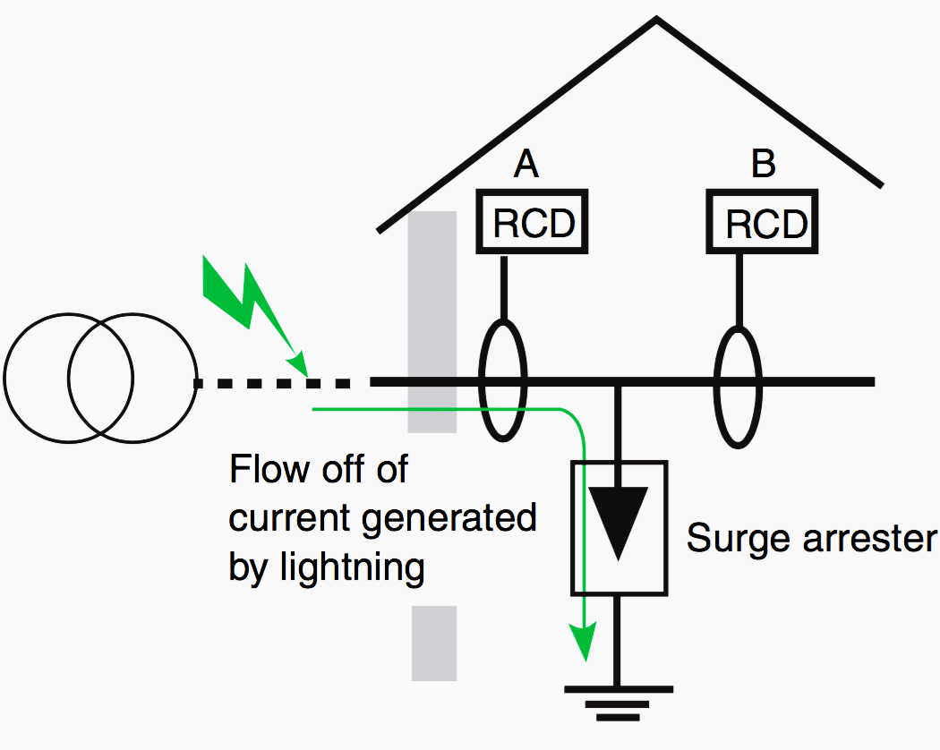
Depending on local utility regulations, RCDs are connected upstream or downstream of surge arresters. If the RCD is placed upstream, it detects the current surge produced by lightning and may trip. A delayed or reinforced-immunity RCD is recommended.
If the RCD is downstream, a standard RCD may be used.
For more information and connection between RCDs and surge arresters feel free to read: Best practice for using surge protective devices (SPDs) and RCD together
3. Disturbances caused by leakage currents
There are a number of types of leakage currents likely to disturb RCD operation:
- Leakage currents at power frequency,
- Transient leakage currents,
- High-frequency leakage currents.
The purpose of these filters is to bring the devices into compliance with the emission and immunity standards made mandatory by European EMC directives.
3.1 Leakage currents at power frequency (50 or 60 Hz)
These currents are generated by the supply source and flow through natural or intentional capacitance. For a single-phase device in a 50 Hz system, continuous leakage currents of approximately 0.5 to 1.5 mA per device are measured.

These leakage currents add up if the devices are connected to the same phase. If these devices are connected to all three phases, the currents cancel out when they are balanced (the algebraic sum is equal to zero).
Given that RCD tripping may take place starting at 0.5 I∆n, it is advised, in order to avoid nuisance tripping, to limit the continuous leakage current to 0.3 I∆n for TT and TN systems and to 0.17 I∆n for an IT system.
Use of an RCD with a narrow operating range (0.7 I∆n to I∆n) reduces this constraint.
3.2 Transient leakage currents
These currents appear when energizing a circuit with a capacitive unbalance or during a common-mode overvoltage (see Figure 7).
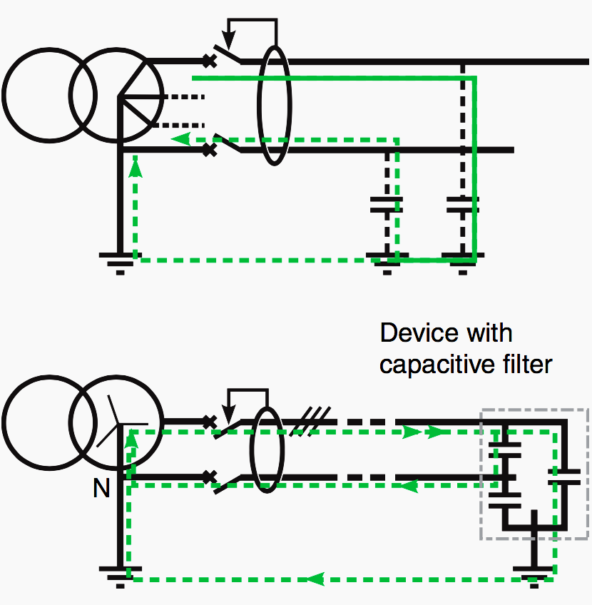

For example, measurements carried out when starting a workstation equipped with a capacitive filter revealed a transient leakage current with following characteristics:
- amplitude of the first peak: 40 A
- oscillation frequency: 11.5 kHz
- damping time (66 %): 5 periods
3.3 High-frequency leakage currents
High-frequency leakage currents (a few kHz up to a few MHz) are caused by the chopping technique used by variable-speed drives or the electronic ballasts of fluorescent lighting. Certain conductors are subjected to high voltage gradients (approx. 1 kV/μs), which generate major current spikes through the stray capacitance of circuits.
Leakage currents of a few tens or hundreds of mA can flow (common mode) and be detected by the RCD, as shown in figure 8 for a variable-speed drive.
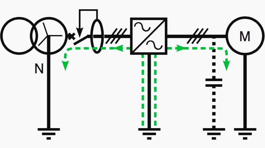

Unlike the 50 Hz – 60 Hz leakage currents for which the algebraic sum is zero, these HF currents are not synchronous over all three phases and their sum constitutes a non- negligible leakage current.
In order to prevent nuisance tripping, RCDs must be protected against these HF currents (equipped with low-pass filters).
4. Variable-speed drives
For combinations of RCDs and variable-speed drives using frequency conversion, it is necessary to simultaneously take into account a number of constraints:
- leakage currents when energising,
- continuous leakage currents at 50/60 Hz,
- continuous HF leakage currents,
- special current waveforms for faults at the drive output,
- current with a DC component for faults on the DC bus.
5. Uninterruptible Power Supplies (UPS)
In installation with backup sources such as UPSs, the protection system must take into account the different possible configurations. In particular operation on AC power or on the batteries, bypass switches closed or not, etc.
In the example in Figure 8, the installation (TT system) includes a UPS. If AC power fails, it is necessary to earth the neutral downstream of the UPS (i.e. close contactor K) to ensure correct operation of the RCDs.
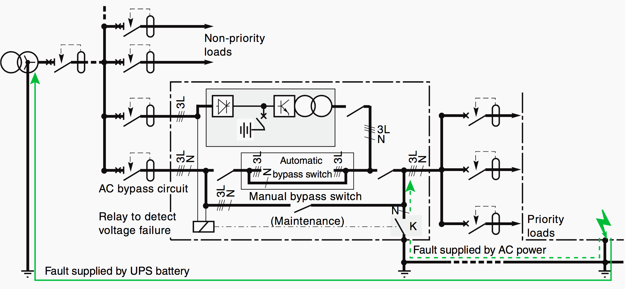

However, this earthing operation is not indispensable to protect persons because:
- the installation becomes an IT system and the first fault is not dangerous,
- the probability of a second insulation fault occurring during the limited time of operation on battery power is very low.
Reference // Residual current devices in LV by Jacques Schonek (Schneider Electric)


Dear Edward,
Thank you very much for sharing of good electrical articles to boost up more knowledge.
I am requesting you to please publish articles on Motors Bearings also.
Thanks & Regards
Jagadish Gampa