Specific industrial transformers
A number of industry applications require specific industrial transformers due to the usage of power (current) as a major resource for production. Electric arc furnaces (EAF), ladle furnaces (LF) and high-current rectifiers need a specific design to supply the necessary power at a low voltage level.

These transformer types, as well as transformers with direct connection to a rectifier are called special-purpose or industrial transformers, whose design is tailor-made for high-current solutions for industry applications.
- Electric arc furnace transformers (EAF)
- DC electric arc furnace transformers (DC EAF)
- Rectifier transformers
- Converter transformers
- Line Feeder
1. Electric arc furnace transformers (EAF)

EAF and LF transformers are required for many different furnace processes and applications. They are built for steel furnaces, ladle furnaces and ferroalloy furnaces, and are similar to short or submerged arc furnace transformers (figure 1).
The loading is cyclic. For long-arc steel furnace operation, additional series reactance is normally required to stabilize the arc and optimize the operation of the furnace application process.
Specific items
EAF transformers are rigidly designed to withstand repeated short-circuit conditions and high thermal stress, and to be protected against operational overvoltages resulting from the arc processes.
The Siemens EAF reactors are built as 3-phase type with an iron core, with or without magnetic return circuits.
Design options
- Direct or indirect regulation
- On-load or no-load tap changer (OLTC/NLTC)
- Built-in reactor for long arc stability
- Secondary bushing arrangements and designs
- Air or water-cooled
- Internal secondary phase closure (internal delta)
Main specification data
- Rated power, frequency and rated voltage
- Regulation range and maximum secondary current
- Impedance and vector group
- Type of cooling and temperature of the cooling medium
- Series reactor and regulation range and type (OLTC/NLTC)
2. DC electric arc furnace transformers (DC EAF)

Direct-current electric arc furnace (DC EAF) transformers are required for many different furnace processes and applications (figure 2).
They are built for steel furnaces with a Thyristor rectifier. DC EAF transformers operate under very severe conditions, like rectifier transformers in general but using rectifier transformers for furnace operation. The loading is cyclic.
3. Rectifier transformers

Rectifier transformers are combined with a diode or Thyristor rectifier. The applications range from very large aluminum electrolysis to various medium-size operations.
Specific items
Thyristor rectifiers require voltage regulation with a no-load tap changer, if any. A diode rectifier will, in comparison, have a longer range and a higher number of small voltage steps than an on-load tap changer.
Additionally, an auto-connected regulating transformer can be built in the same tank (depending on transport and site limitations).
Design options
- Thyristor or diode rectifier
- On-load or no-load tap changer (OLTC/NLTC)/filter winding
- Numerous different vector groups and phase shifts possible
- Interphase reactor, transductors
- Secondary bushing arrangements and designs
- Air or water-cooled
Main specification data
- Rated power, frequency and rated voltage
- Regulation range and number of steps
- Impedance and vector group, shift angle
- Type of cooling and temperature of the cooling medium
- Bridge or interphase connection
- Number of pulses of the transformer and system
- Harmonics spectrum or control angle of the rectifier
- Secondary bushing arrangement
4. Converter transformers

Specific items
Converter transformers are mostly built as double-tier, with two secondary windings, allowing a 12-pulse rectifier operation. Such transformers normally have an additional winding as a filter to take out harmonics. Different vector groups and phase shifts are possible.
Main specification data
- Rated power, frequency and rated voltage
- Impedance and vector group, shift angle
- Type of cooling and temperature of the cooling medium
- Number of pulses of the transformer and system
- Harmonics spectrum or control angle of the rectifier
5. Line Feeder
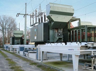
This kind of transformer realizes the connection between the power network and the power supply for the train.
Main specification data
- Rated power, frequency and rated voltage
- Impedance and vector group
- Overload conditions
- Type of cooling and temperature of the cooling medium
- Harmonics spectrum or control angle of the rectifier
Design options
- Direct connection between transmission network and railway overhead contact line
- Frequence change via DC transformation (e.g. 50 Hz – 16,67 Hz)
- Thyristor or diode rectifier
- On-load or no-load tap changer (OLTC/NLTC)/filter winding
- Secondary bushing arrangements and designs
- Air or water-cooled.
Reference: Siemens Energy Sector – Power Engineering Guide Edition 7.0





Srikalahasti,
Andhra Pradesh
Could you explain the working principle of a transformer with high impedance. Thanks in advance
Dear Edvard,
We have in our facility a 3 winding transformer connected to 12-pulse VFD.The 12-pulse VFD is driving two AC motors(690KW,each;V=690VAC,Hz=50)
Rated KVA=1950;Primary Voltage=11KV;Secondary Voltage:726;
Primary Delta
Secondary Winding (Delta),Z=6.14%
Secondary Winding(Y),Z=6.34%
I am planning to perform a short circulation using per unit method but i have not idea how to make the “impedance diagram”.Is this transformer series or parallel in the impedance diagram….CAN YOU PLEASE HELP ME…THANKS