
What is the islanding?
Each neutral earthing system has advantages and disadvantages for the safety of property, electromagnetic compatibility or continuity of service. The main system must therefore be chosen according to these criteria, but the characteristics of the system, the receivers, and the requirements for their operation may not be compatible with this system alone within the same installation.
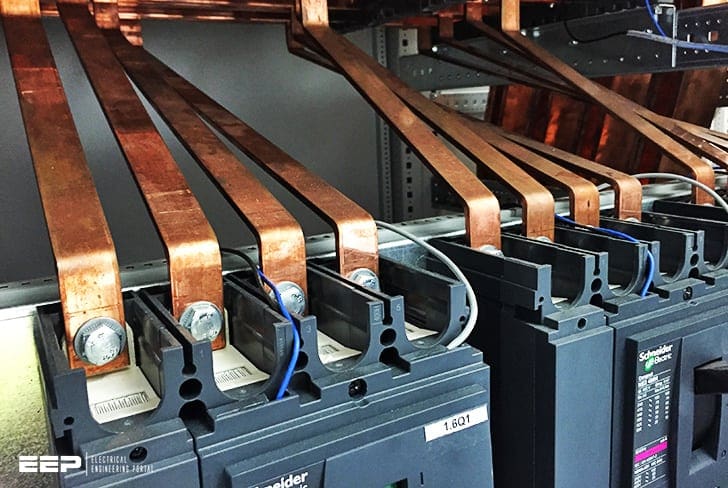 How to create a specific neutral earthing system within existing one (islanding) - photo credit: EEP
Creating a specific system in part of the installation, or islanding, may be an appropriate solution. Let’s talk about it.
1. Supply via same the transformer
Whether it is possible to create different neutral earthing systems in one installation (islanding) is initially dependent on whether or not the island can be supplied via a separation transformer.
In practice, only TN and TT systems can cohabit, subject to compliance with the following six conditions:
- The neutral is earthed directly.
- Each part of the installation is calculated and protected according to the specific rules of each system.
- A main equipotential link is established in each building, and the protective conductors connected to it.
- Each part of the installation (island) has its own protective conductor to which the exposed conductive parts are connected.
- If there are exposed conductive parts of different installations in the same building, they must be linked by means of an additional equipotential link.
- The rules specific to the use of the PEN conductor (TN-C system) must be complied with, in particular the non-breaking of the PEN or its connection to the general equipotential link downstream of the breaking device.
1.1 Schematic diagram of the power supply in the same building or in two buildings close to one another
Non-breaking of the PEN (1) or connection to the general equipotential link downstream of the breaking device (2). All the protective conductors are connected to the same equipotential link (3).
1.2 Schematic diagram of the power supply of several buildings
If only the TN-C system is used in the 1st building, the power supply cable of the second building can use the neutral conductor as the protective conductor (PEN) – cables with 4 conductors.
If several earthing systems (identical or different) are used in the same building, the protective circuits (PE conductors) must be linked together and interconnected to the same equipotential link of the building concerned.
NOTE! Changing from the TN-C system to the TN-S system is not considered to be a change of neutral earthing system, but in all cases, the TN-S system must be downstream of the TN-C system.
1.3 Connecting an installation to the public distribution system using a TN-C or TN-S system
Public distribution often uses the TT system. The use of a TN system link requires the agreement of the local distribution service:
- It is generally connected on underground systems.
- The low voltage neutral is connected to the earth of the low voltage (1000 < Un ≤ 50,000 VAC) exposed conductive parts of the substation.
- The PEN conductor is not broken, right up to the delivery point.
- The characteristics of the system (distances, powers, changes) are required in order to calculate the possible fault loop.

(1) if the delivery substation and the main lV distribution board are located in the same building, the exposed conductive parts of the substation must be linked to the same earth connection as the lV installations.
1.4 Cohabitation of earthing systems
Example of cohabitation of systems: individual installation: TT system (subscribers), collective installation: TN (for example, heating)

2. Supply via a specific transformer
In this application, there are three situations.
Situation #1 – The use of a “circuit separation transformer”, to separate the load circuit locally from the supply circuit in order to avoid the risk of indirect contact on the separate circuit. this precaution is applicable for the supply of a device or a set of devices grouped together.
Situation #2 – The use of an isolating transformer with separate windings to supply a specific device that is sensitive to electromagnetic disturbance. the transformer is thus used for its filtering properties.
Situation #3 – The use of an isolating transformer with separate windings intended to re-create a supply source at the start of which the neutral earthing system appropriate to the specific requirement of the island can be set up, generally TN-S or IT.
2.1 Supply via TN-S system (local neutral connected)
This system is used for installations with high leakage currents (data processing), low insulation (furnaces, welding machines) or those that are subject to a great deal of disturbance (microwave transmitters).
Applications where interference suppression is important (capacitors) may also need this type of system (industrial control or telecommunications equipment).
Particular attention must be paid to the equipotentiality of the receivers. additional links will have to be set up for this.
Neutral/protective conductor interconnections must be established as well as additional referencing to earth, if necessary.

Practical rule for determining the rating of the protection on the secondary
To check that the chosen device is suitable, an approximate value of the minimum short circuit at the furthest point of the installation can be obtained, using the following formula:
Where:
- Us – transformer secondary voltage in V
- P – transformer power in VA
- Ucc % – transformer short-circuit voltage
- l – length of the line in m
- S – cross-section of the line in mm2
- ρ copper – 0.023 Ω mm2/m
- gG fuse: In ≤ Ik min / 4
- Type C circuit breaker: In ≤ Ik min / 8
2.2 Power supply in IT system
This arrangement is used for installations where there is a:
- Need for continuity of service for safety (medical, food processing)
- Need for continuity of operation (ventilation, pumps, markers)
- Risk of fire (silos, hydrocarbons)
- Low short-circuit power (standalone generators)
Although the primary property of the it system is to limit the 1st fault current and not “break”, the fact remains that this choice may be made to the detriment of other requirements that must be given due consideration:
- The non-distribution of the neutral conductor, which is still recommended due to the risk of rise in voltage or breaking in the event of a double fault, is not very compatible with the use of single phase receivers.
- The risk of rise in the voltage of the earth to which the exposed conductive parts of the electronic devices are connected by their protective conductors.
- The difficulty of using high sensitivity residual current devices (30 mA) for power sockets that would break at the 1st fault.
Warning you should consider!
It is recommended that the IT island is only created over a small area. If the neutral conductor is necessary, it must be systematically protected (and not just broken) and it must not have a small cross-section (it could melt if there were a double fault).
To limit the risk of a rise in the voltage of the exposed conductive parts they must be interconnected and linked to the local earth connection, which must itself be connected to all the earth connections of the building via the main equipotential link.

Medical it system
The application of the medical IT system is defined in France by standard NF C 15-211 (measure P5). It is mandatory in anaesthetics rooms, operating theatres
and cardiac catheterisation rooms. it is recommended in several other areas: hydrotherapy, recovery rooms, intensive care or haemodialysis units, etc.
The transformer and switchgear must be in an area separate from the room or unit, but an illuminated indication of the insulation monitoring device must be
visible in the room or unit.
The impedance Z of the Permanent Insulation Monitor (PIM) must be at least 100 kΩ with an alarm threshold set at 50 kΩ corresponding to a fault current of approximately 5 mA (If = U0/Z = 230/5000 = 4,6 mA) enabling any fault to be detected before the high sensitivity residual current devices break.
Compatibility between high sensitivity RCDs and non-tripping at the 1st fault in it islands
Protection of power sockets by high sensitivity residual current devices is mandatory, but unexpected breaking due to tripping can be anticipated by setting the detection current of the Permanent Insulation Monitor (PIM) to a value lower than that of the residual current device (see medical IT system).
If continuity of operation is vital, high sensitivity residual current devices are not necessary if the devices are connected directly to the installation (with no power socket).
The special use exemption measure can be applied to supply power sockets that are not protected if no device other than those intended are likely to be connected.
Reference // Electrical energy supply by Legrand


Sorry my query is not related to the above subject but different. I hope to get your response for my clear understanding.
This is in a 230KV GIS indoor substation.
-Generally ACSR conductor is used as droppers to GIS bushings. In some instances a tubular Aluminium pipe is used as dropper to GIS bushing.
Question is what is the purpose of tube?
I shall appreciate for your answer.
With regards
Everyday ,I receive articles on Power System Engineering ,But in real life situations ,we do not work in every aspect of electrical engineering,we need professional help for design ,data sheet or drawings for projects .I would like to if I can get get it from some one who is also working on it .My whatsApp number is +91-7588231923
whats is the differnace between normal UPS & Medical UPS system? what are the set points for Medical UPS?
why medical isolation power units are limited to 10kva range? whats the difference between isolation transformer & medical isolation Transformer?
In the formula for calculating the minimum short-circuit current, the denominator has a real part and an imaginary part, that is, Z = R + jX), so the sum is not algebraic
Very practical and learning valuable information. A lot of thanks to Mr. Edvard Csanyi for publishing so that such remarkable useful very tips.
Chakib Abi-Saab Soto
Caracas, Venezuela
I would like to outline that in fig. 1, the supposed TT system is NOT a TT but still TN system: the presence on RCD is not relevant (in either systems RCD can be used for personal protection against electircal shock)
In fig 2, there is a “double” ground connection for neutral, that should, in general, be avoided
In IT system, there is limit in the total connection length, not to incur in capacitive currents (specially in medical environment).
EN regulation also require to NOT distribute the neutral in IT systems (for medical areas, single phase distribution is the only choice)
That’s my point of view, of coarse