
Estimated Study Time: 48 minutes
Substation design hints
From the point of making specification, high voltage substation is pretty complex. There are dozen of substation equipment that must be specified and selected out of hundreds of manufacturers. This article will help a little bit with some fundamental instructions on selecting the main components of an HV substation.
 Instructions for generating specifications and selecting the main components of an HV substation
When the maximum load currents have been determined the rated current of the switching equipment should be selected from the IEC series. Nowadays, it is probable that the lowest current rating available on the market may be over-dimensioned for most purposes, especially in the networks of developing countries.
Let’s take an example of high voltage busbars. The current rating of busbars depends on the scheme. The rated current of the main busbar is normally chosen to be 1.5 to 3 times higher than that of the line bays. The physical grouping of the feeders may affect this choice.
Busbars are often over-dimensioned during the first stage of a substation’s life, because their reinforcement later on may be difficult and expensive and the additional cost of over-dimensioning is relatively small. The rating of meshed scheme configurations can be difficult (e.g. 1 ½ circuit breaker) and it is necessary to define which switching conditions and network contingencies have to be taken into account, making allowance for maintenance outages.
The nominal current of the by-pass busbar and coupling bay is at least the same as the highest rating of any of the circuits that may be connected.
Therefore, the current rating of the transformer bays should be some 20-30 % higher than the rated current of the transformer.
System planning will determine the number, capacities and future extension requirements for compensating equipment. It is to be noted that, in accordance with IEC recommendations, the current rating of the shunt capacitor bank switching equipment should be 1.5 times that of the capacitor.
- Rated HV Equipment Characteristics
- Circuit Breakers
- Disconnectors and Earthing Switches
- Surge Protection Devices
- Instrument Transformers
- Line Traps (Wave Traps)
- Busbars and Connectors
- Post Insulators
- High Voltage Cables
- Earthing Grid
- Power Transformers And Compensating Equipment
- Specification and Selection Of Auxiliary Equipment
1. Rated HV Equipment Characteristics
The following are the common rated characteristics of switchgear and controlgear (including their operating devices and auxiliary equipment) which should be specified (IEC 62271-1)
- Rated voltage,
- Rated insulation level,
- Rated frequency,
- Rated normal current,
- Rated short-time withstand current,
- Rated peak withstand current,
- Rated duration of short circuit,
- Rated supply voltage of closing and opening devices and of auxiliary circuits,
- Rated supply frequency of closing and opening devices and of auxiliary circuits,
- Rated pressure of compressed gas supply for closing and opening devices,
- Pollution level, and
- Corona and RIV requirements.
Equipment should be type tested in order to verify its compliance with the specified ratings. Note : Other rated characteristics may be necessary and are specified in the relevant IEC standards.
Figure 1 – 220kV SF6 circuit breaker
Go back to the Contents Table ↑
2. Circuit Breakers
A circuit-breaker is a mechanical switching device, capable of making, carrying and breaking currents under normal circuit conditions and also making, carrying for a specified time and breaking currents under specified abnormal circuit conditions such as those of short-circuit.
Circuit breaker ratings must be examined closely. Voltage and interrupting ratings are stated at a maximum operating voltage rating, i.e., 38 kV rating for a breaker applied on a nominal 34.5 kV circuit.
Oil circuit breaker development had been relatively static for many years. The interrupter’s design takes advantage of the arc that occurs when the contacts are broken and the breaker kicks on. Because the mineral oil insulating the electrical arc is breaking down, hydrogen gas is produced.
The interrupter is intended to extinguish the arc when the current drops below zero by using the gas as a cooling mechanism to cool the arc and the pressure to extend the arc through a grid (arc chutes).
Vacuum circuit breakers use an interrupter that is a small cylinder enclosing the moving contacts under a hard vacuum. When the breaker operates, the contacts part and an arc is formed resulting in contact erosion.
Gas circuit breakers employ SF6 gas an interrupting and insulating medium. In “single puffer” mechanisms, the interrupter is designed to compress the gas during the opening stroke and use the compressed gas as a transfer mechanism to cool the arc and also use the pressure to elongate the arc through a grid (arc chutes), allowing extinguishing of the arc when the current passes through zero.
In other designs, the arc heats the SF6 gas and the resulting pressure is used for elongating and interrupting the arc.
Suggested Reading – Main circuit breaker types from 1000 V MCB to 1000 kV dead tank breaker
Main circuit breaker types from 1000 V MCB to 1000 kV dead tank breaker
Go back to the Contents Table ↑
2.1 Switching Conditions
The breaking capacity of a circuit-breaker is defined by a large number of parameters. The value of breaking current must be related to the transient recovery voltage (TRV) which depends mainly on the electrical characteristics of the circuit to be switched.
The magnitude and waveform of TRVs will vary at a specific point of the network dependent on system configuration (the number, type and load of interconnected circuits) and on the fault location. These configurations may give different resonant circuits and the circuit-breaker must be able to break the current in all cases.
Figure 2 – Transient Recovery Voltage
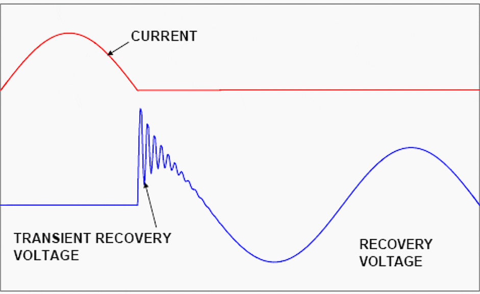
The shape of TRV waveform is partially influenced by the circuit-breaker itself as it depends on the deformation of the current waveform immediately before the interruption.
More beneficial conditions are given by minimum-oil or SF6, “puffer” arc extinction chambers than by air-blast types. The switching process is considered to give rise to a steep fronted TRV when the fault is located up to a few kilometres on the line side of a circuit-breaker.
The interruption of capacitive and inductive currents is an onerous duty for circuit breakers. Restrikes or reignitions may be source of dangerous overvoltages.
In some circumstances the use of controlled (point on wave) switching is recommended in order to limit overvoltages and reduce inrush currents. This facility can be provided by means of special electronic relays that control the instant of switching. IEC 1233 may be referred for inductive load switching.
Suggested to study – The facts about transients in power systems
The facts about transients in power systems you should properly understand
Go back to the Contents Table ↑
2.2 Circuit Breaker Types
The present day choice at transmission voltages is SF6 (or a mixture of SF6 and nitrogen for very low ambient temperature) circuit breakers. Nowadays, single pressure SF6 interrupters are most used. Vacuum circuit-breakers are widely used in MV networks. There are two kinds of circuit-breaker known as “dead tank” or “live tank” depending on the enclosure of the arc extinguishing chamber.
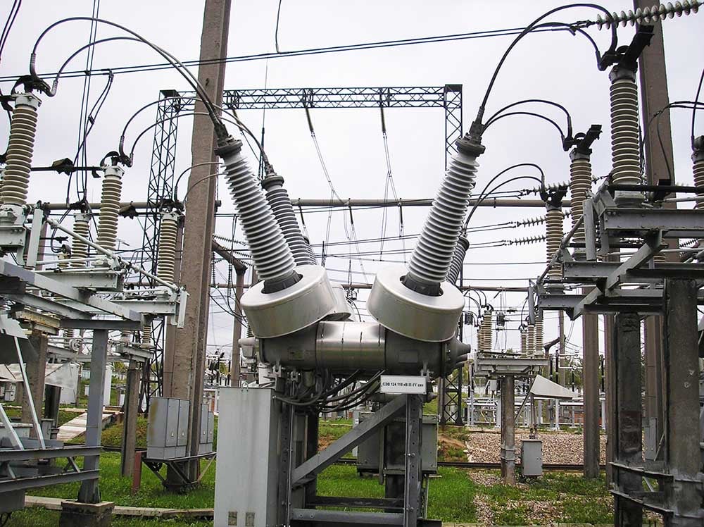
Circuit-breakers of the ‘live tank’ type are normally supplied for outdoor open-terminal substations and the interrupters are housed in porcelain or composite weather-shields on lop of an insulated support column.
Figure 3 – Live-tank circuit breaker

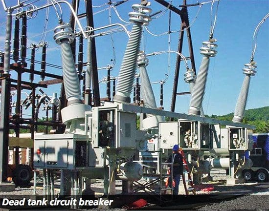
Circuit-breakers of the ‘dead tank’ type have interrupters housed in an earthed metal enclosure and either form part of a GIS substation or their connections are taken out through bushings. In this arrangement the bushings may be used to house the current transformer secondary windings.
“Dead tank” circuit-breakers are seldom used in Europe and are more popular in the USA and Japan.
Any circuit-breaker drive most be fitted with an energy storage device which permits a complete standard sequence of operation without further input of energy.
Figure 4 – Dead-tank circuit breaker
Rated operating sequences are defined in IEC 62271-100. IEC 62271-100 gives comprehensive details of the selection of circuit-breakers for service in terms of their electrical and mechanical performance. In some special cases the circuit breaker are equipped with electronic sensors for on-line monitoring.
The data recorded are for example: density of gas in circuit-breaker, energy stored in driving mechanism, contact erosion, parameters of motor charging spring in drive mechanism.
Related electrical guides & articles


Edvard Csanyi
Hi, I'm an electrical engineer, programmer and founder of EEP - Electrical Engineering Portal. I worked twelve years at Schneider Electric in the position of technical support for low- and medium-voltage projects and the design of busbar trunking systems.I'm highly specialized in the design of LV/MV switchgear and low-voltage, high-power busbar trunking (<6300A) in substations, commercial buildings and industry facilities. I'm also a professional in AutoCAD programming.
Profile: Edvard Csanyi
