
Estimated Study Time: 13 minutes
Substation automation & IEC 61850
It is not easy to read the IEC 61850 documents or to comprehend how the pieces all work together. When implementing systems as complex and as new as substation automation, substation engineers will need to work closely together with the vendors of such equipment and systems.
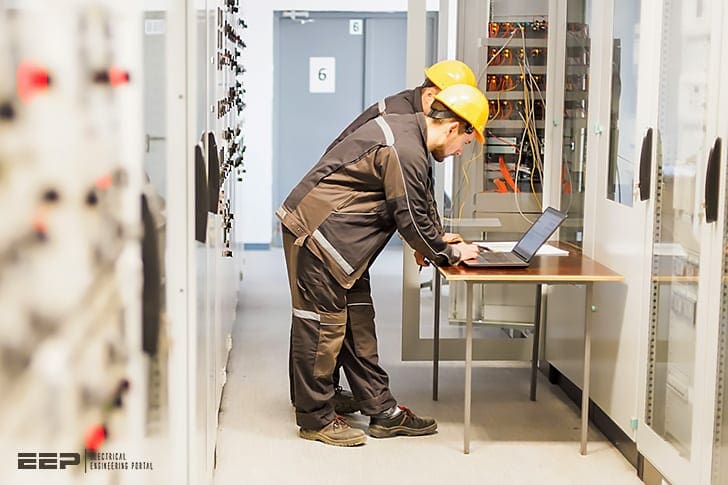 Six steps for specifying IEC 61850 and substation automation requirements
Although the vendors will perform the detailed implementation of the IEC 61850 object models and service models, the substation engineers must be able to decide what settings should be established for a particular substation.
Therefore, substation engineers should develop a deeper understanding of IEC 61850, of the potential benefits of the various features if they can be fully utilized, and of the issues that must be resolved as substation automation equipment and system are implemented for the utility.
Procedure for Specifying IEC 61850
The general procedures for specifying substation automation are described below. The following paragraphs addresses the procedure for specifying IEC 61850, which consists of the following steps:
- Determine functional requirements
- Determine IEC 61850 logical nodes and the data available within the logical nodes
- Develop IEC 61850 data exchanges within the substation
- Develop IEC 61850 data exchanges with external systems
- Specify conformance testing
- Specify IEC 61850 configuration tools
Step 1 – Determine Functional Requirements
Determining the functional requirements, which must be performed by utility substation engineers, is the most critical step. Following this step, the results may be passed to vendors or integrators to do the detail work (including the implementation of the IEC 61850 technologies).
Developing functional requirements is the necessary first step before the IEC 61850 requirements can be determined.
The requirements include:
- Layout of the substation from an electrical point of view.
- Identification of the types of equipment – CTs, VTs, circuit breakers, capacitor banks, transformers, and tap changers.
- Identification of what data are available or necessary.
- Consideration of protection schemes – Identify what events will cause what actions by what equipment.
- Identify SCADA requirements – Identify what information will be needed in real time by the substation master and/or the control center SCADA system, and what control/set-point/parameter capabilities will be needed.
- Determine information flow requirements – Identify what information is required from each substation device and what information should be sent to each substation device. This includes information exchanges within the substation and between the substation and the rest of the utility
- Determine information security requirements – Identify the data assets and what level of security is required.
- Consider system and network management requirements – Identify what capabilities are needed for monitoring, alarming, controlling, automating, diagnosing, maintaining, repairing, and auditing the information infrastructure.
Specifying the functional requirements for substation automation requires a different approach than substation engineers have used in the past to construct new substations.
By definition, functional requirements should focus on what rather than on how. The most effective way to develop these functional requirements is to use modeling techniques.
These modeling techniques allow functions to be described with their interactions illustrated through formalized drawings (see Figure 1).
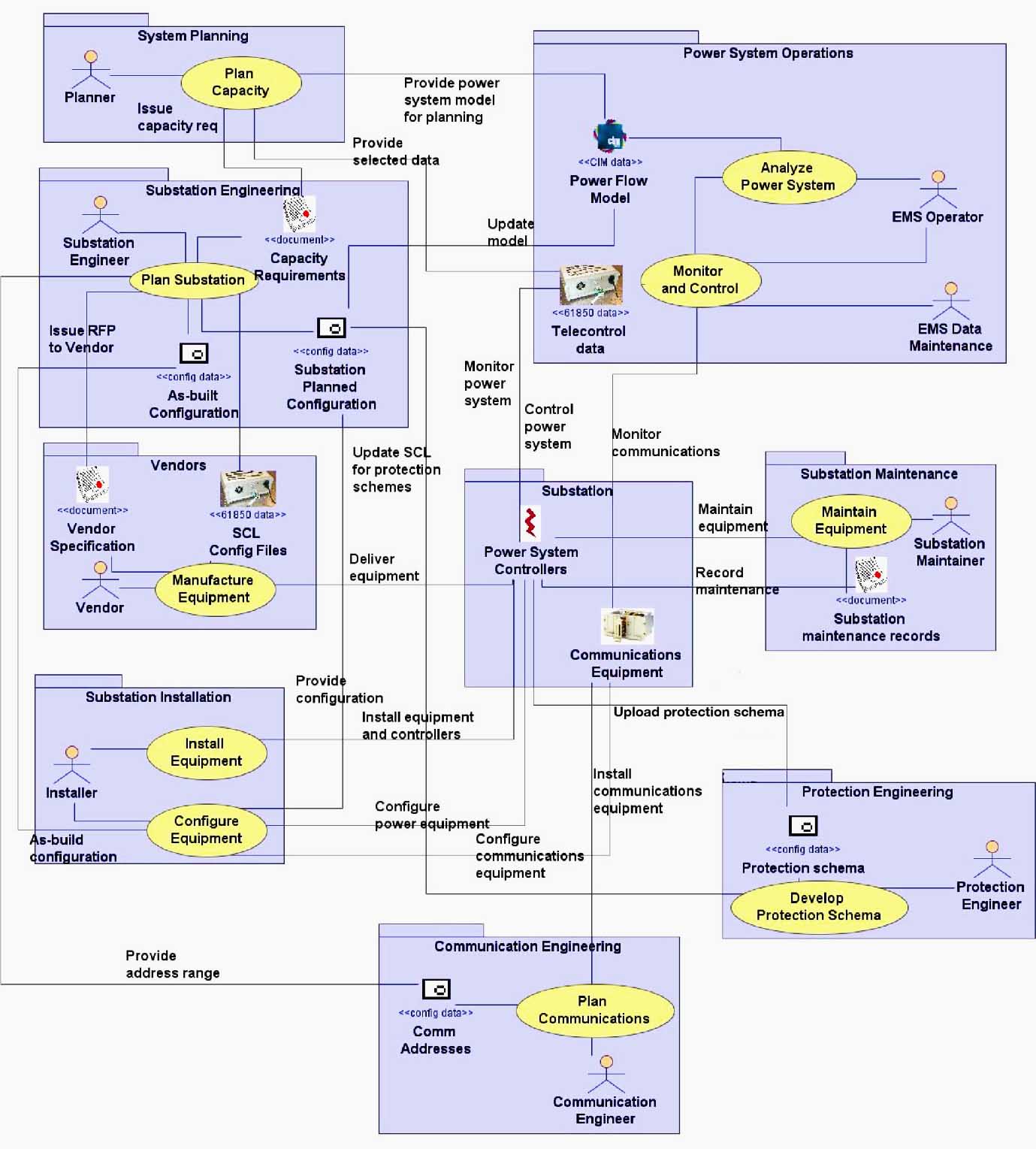
Using models allows functions to be drawn and redrawn (on paper or on computer screens) so that all stakeholders can review them. The function must be refined as requirements are better understood and finalized into formal functional specifications before actual designs are created and long before any hardware or software is purchased.
Substation automation involves not only equipment, but also the communications infrastructure to monitor and manage the equipment, particularly when all of the IEC 61850 capabilities are to be utilized.
Therefore, in addition to the design of physical and electrical requirements, substation automation also requires the analysis of information requirements and a determination of the flow of information between equipment and systems.
Modeling techniques can also be used to develop the best infrastructure or these communication information requirements.
IEC 61850 Data Modeling Part 1
This tutorial focuses on the data model. The tutorial is structured into five parts. In Part 1, I will give you an introduction on what IEC 61850 is and the different tasks you have as a device manufacturer.
IEC 61850 Data Modeling Part 2
Part 2 introduces the elements of the data model.
Step 2 – Determine IEC 61850 Logical Nodes and the Available Data
The utility substation engineers can perform this step by following this guideline. However, vendors or system integrators can also perform this step as long as the utility substation engineers verify that the results conform to the functional requirements.
The logical node determination includes:
- Based on the functional requirements, determine which logical nodes are needed for which devices. Although vendors and/or integrators may choose to instantiate (turn into actual data) different logical nodes in different controllers or IEDs, the list of logical nodes should be the same for meeting the same functional requirements.
- Select which optional data items must be instantiated in the logical nodes, again based on the functional requirements.
Step 3 – Determine IEC 61850 Data Exchanges Within the Substation
The data to be exchanged between devices in the substation must be defined, particularly between the protection devices and the circuit breakers, but also between other closed-loop automated functions within the substation, as well as monitoring, alarming, reporting, and logging of information to the substation master.
This step should most likely be performed jointly between the utility substation engineers and the vendors/implementers of the substation equipment.
The functional requirements in Step 1 describe the types of data to be exchanged. This step defines explicitly what IEC 61850 data items are sent, where, and under what conditions within the substation.
The PICOM descriptions are not normative, however, meaning that they are there for convenience and as examples.
Therefore, it is important to ensure that the actual data exchanges are clearly defined as to the average and maximum transfer times, the average and maximum response times, the average and maximum size of messages, security, availability, backup and/or redundancy, and other performance criteria.
Step 4 – Determine IEC 61850 Data Exchanges With External Systems
The use of modeling techniques can help tremendously in determining complex interactions among different systems. These techniques can be used in particular with the data exchanges involving IEC 61850 objects.
Specifically, the following issues and questions should be addressed:
Monitored data:
- Which users (humans, systems, or applications) need what data?
- What are the sources of these data? Can substitute data be provided if the primary source is unavailable?
- When are these data required (continuously, upon change, or upon user request)?
- How critical are the data? Must they be rigorously protected against unauthorized changes? Should all changes be logged for audit purposes?
- How secure should the data be? Available to anyone? Restricted to certain groups?
- What should occur if the data are not available or invalid (cause an alarm, be recorded in a log, be ignored, cause an application to execute, cause equipment to revert to local mode, cause a system to shut down, failover, or restart)?
- What should occur if the data indicate a power system problem?
Controls and parameter settings:
- Who should be allowed to issue controls or change settings of what devices?
- When should these controls or setting changes be permitted (at any time, only during substation maintenance, only if certain equipment is tagged, only if other data indicate that they are allowed such as in remote control mode)?
- How critical are these controls or setting changes? Must full individual authentication be used? Is role-based access through a common password adequate? Are passwords not necessary?
- What should occur if the control action fails (cause an alarm, be recorded in a log, be ignored, cause an application to execute, cause equipment to revert to local mode, cause a system to shut down, failover, or restart)?
Step 5 – Specify Conformance Testing
Requiring that a vendor pass an IEC 61850 conformance test is vital to ensuring interoperability. The conformance test procedures were standardized in 2004 as IEC 61860 Part 10.
Step 6 – Specify IEC 61850 Configuration Tools
It is vital that the vendor provide tools for managing the object models, communication services, protocols, and information services such as network management and security.
How to do Goose for ABB relay in PCM600
How to do Goose for ABB relay in PCM600? Goose is done for overcurrent protection block.
Condition: when the bus tie is in a close position during that time if over current protection occurs that should not trip incomer suddenly wait for the bus tie to trip if its fail to trip then the only incomer has to trip for that I have Two high stage protection one PHHPTOC1 and PHHPTOC2 both have same current setting but time is till high for PHHPTOC2.
For normal fault, PHHPTOC1 will operate on Incomer but if Bus tie is connected with incomer during that time incomer detected fault current and bus tie also detected fault current then the fault occurs on other buses not due to his own bus. so incomer over current protection PHHPTOC1 should block but if Bus tie fails to trip then PHHPTOC2 will operate which will have little high timing than PHHPTOC1.
This blocking is taken from Bus tie over current and give for Block to Incomer over current.
Source: Guidelines for Implementing Substation Automation Using IEC 61850, the International Power System Information Modeling Standard by Electric Power Research Institute (EPRI), Inc.
Related electrical guides & articles


Edvard Csanyi
Hi, I'm an electrical engineer, programmer and founder of EEP - Electrical Engineering Portal. I worked twelve years at Schneider Electric in the position of technical support for low- and medium-voltage projects and the design of busbar trunking systems.I'm highly specialized in the design of LV/MV switchgear and low-voltage, high-power busbar trunking (<6300A) in substations, commercial buildings and industry facilities. I'm also a professional in AutoCAD programming.
Profile: Edvard Csanyi

Edvard Csanyi can you help me, please, with the last videos “IEC 61850 Engineering with PCM600 – Part 1 and Part 2”, I can visualizate in this moment. Thank you very much for this information and your awesome electrcial ingieniering page.
Thanks for all information
Merci pour ces important informations
it is very helpful and precious course,thank you for this detailed description , may I find detailed description for controlling and installation of OPGW conductors with its accessories and splices, also OPGW-OPGW BOXES, OPGW-FOC boxes
I would like to Introduce and Marketing this automation system in India – Chhattisgarh up on actual demo for any one of the Customer.
Ed,
Thanks for your excellent collection of in dept topics everyday. Believe me, Every morning I wait eagerly to read your article of the day. Some times I can finish reading it right away. But, most of the times I collect it and read it later during the week or further. But, I really really enjoy reading your articles. Thanks a lot for your contributions. Electrical portal is my favorite. Thanks many to you. Please don’t stop doing this.
Thanks and best Regards
Muneer
Very good information