Starting winding in series with a centrifugal switch
The split-phase (SP), or more accurately, the resistance-start, split-phase, induction run motor,is recommended for medium-duty applications. It can run at constant speed even under varying load conditions where moderate torque is acceptable. Split-phase motors have squirrel-cage rotors and both a main or running winding and a starting or auxiliary winding.

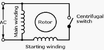
The schematic diagram for an SP motor, Figure 1, shows the starting winding in series with a centrifugal switch and the main winding in parallel across the AC line.
The starting winding is wound with fewer turns of smaller-diameter, higher-resistance wire than the main winding.

When energized, current flowing in the starting winding is essentially in phase with the line voltage, but current flowing in the parallel main winding lags behind line voltage because it has lower resistance and higher reactance. This lag “splits” the single phase of the AC line by introducing about a 30° electrical phase difference between the currents in the two windings.
Although it is small, this phase difference is enough to provide a weak rotating magnetic field which interacts with the rotor, causing it to rotate.
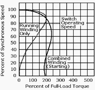
The typical torque-speed curves for an SP motor, Figure 2, show that starting current is high and running torque is moderate When rotor speed reaches about 80 percent of its rated full-load synchronous speed, its built-in automatic centrifugal switch disconnects the starting winding, protecting it from destructive overload.

The SP motor then continues to run on the single oscillating AC field established by its main winding. SP motors are rated from 1/20 to 1/3 hp when operating from a 120/240-V AC line, and full-load speed is from 865 to 3450 rpm.
These motors are recommended for applications where motor stops and starts are frequent. SP motors are used to drive fans, blowers, pumps, office machines, and power tools where the load is applied after the motor has reached its operating speed.
Reference: Handbook of electrical design details – Neil Sclater, J. E. Traister


