
Estimated Study Time: 37 minutes
Testing Protective Schemes
This technical article discusses the essentials of transformer differential protection and restricted earth fault protection schemes, contrasting the two and elaborating on why the latter is necessary. Furthermore, it reveals the outcomes of stability tests performed on a 502 MVA power transformer. So, let’s get into it!
 Mastering stability test of power transformer: Differential and REF protection
Power transformers play a crucial role in substations as they facilitate voltage transformation while maintaining power levels between high and low voltage stages. To liken their significance, we can equate power transformers to the heart in a human system. From an economic perspective, power transformers are among the most costly equipment found in substations.
A failure in a power transformer leads to power supply disruptions and instability in the electrical power system within the network. Consequently, safeguarding transformers against various faults becomes paramount.
Traditionally, transformers are protected by various mechanical protective devices like Buchholz relays, oil temperature sensors, winding temperature sensors, and pressure relief devices. However, in addition to these mechanical safeguards, electrical protections are essential for comprehensive transformer protection.
Specifically, out-of-zone faults, also known as through faults, require the differential protection scheme to remain stable, meaning it should not operate during through fault conditions.
Differential protection operates on the principle of current conservation, where the incoming current must equal the outgoing current. However, a key distinction arises when dealing with transformers. The currents at the high-voltage (HV) and low-voltage (LV) sides are not equal. Therefore, we must apply a transformation ratio to calculate the differential current between the HV and LV windings.
In this article, we will delve into the stability tests performed on Transformer Differential Protection Relays and Transformer Restricted Earth Fault Protection Relays. These tests serve to verify correct polarities, validate setting calculations, and ensure the ratio and phase angle compensation of the differential protection.
The article will cover fundamental topics related to differential protection and restricted earth fault protection schemes, highlighting the differences and explaining the necessity of restricted earth fault protection alongside differential protection. Additionally, we will share the results of stability tests conducted on a 502 MVA power transformer.
By exploring these crucial aspects, we aim to provide a comprehensive understanding of transformer protection and the vital role played by stability tests in ensuring the reliability and effectiveness of protective schemes.
- Exploring Transformer Differential Protection
- Differential Protection Scheme
- Restricted Earth Fault Protection
- Why REF protection is required if differential protection is already available and has a similar zone of protection?
- Importance of Stability Testing
- Calculations for Stability Test of 502MVA Power Transformer
- Simulating Stable Conditions Among HV-LV&TV Windings
- Simulating the Unstable Condition: Injecting Fault at TV Side
- Simulating the Unstable Condition: Injecting Fault at HV Side
- Simulating the Unstable Condition: Injecting Fault at HV & TV Sides
- Simulating the Stable Condition Between HV-LV Windings
- Simulating the Unstable Condition Between LV and HV: Injecting Fault at HV Side
- Simulating the Stable Condition Between LV-TV Windings
- Simulating the Unstable Condition Between LV and TV: Injecting Fault at TV Side
- Simulating the Stable Condition for Restricted Earth Fault Protection
- Simulating the Unstable Condition for Restricted Earth Fault Protection
- BONUS! Power System Protective Relaying Book (PDF)
1. Exploring Transformer Differential Protection
As previously discussed, transformers in substations rank among the most costly electrical equipment. Therefore, safeguarding this equipment is of paramount importance, necessitating both mechanical and electrical protective measures. As a general guideline, when the transformer rating exceeds 5 MVA, the use of a differential protection relay is strongly recommended.
Differential protection stands as the primary safeguard for transformers and operates continuously without any time constraints.
Transformer differential protection must account for several factors, including:
Factor #1 – Ratio Compensation: This compensates for the current difference at HV and LV levels due to the transformation ratio.
Factor #2 – Phase Angle Compensation: This addresses variations in phase angles between the primary and secondary sides of transformers, introduced by the vector group of transformers.
Factor #3 – Error Compensation: It accommodates any errors associated with current transformers (CTs).
Factor #4 – Transformation Ratio Adjustment: This accounts for changes in the transformation ratio due to on-load tap changer operations.
Factor #5 – Zero-Sequence Filtering: Ensures effective handling of zero-sequence currents.
By considering and compensating for these factors, transformer differential protection ensures the accurate and reliable operation of protection schemes, safeguarding the transformer and the power system it serves.
Figure 1 – Connection example of Siemens 7UT613 Differential protection relay installed at delta star power transformer

2. Differential Protection Scheme
The components of a transformer differential protection scheme include current transformers and differential relay, and it protects transformer windings and any additional equipment positioned within zone form by the CTs. For example, if the differential relay is connected to the bushing CTs of the transformer, the protection zone is confined to the transformer itself.
However, when the differential CTs are located within the HV and MV switchgear or Gas-Insulated Switchgear (GIS), the scope of the differential protection expands to encompass not only the transformer but also the transformer’s bushings, the conductors or cables connecting the bushings to the switching devices at both HV and LV levels.
Understanding the differential protection scheme becomes more accessible when examining the relay connections in the single-line diagram.
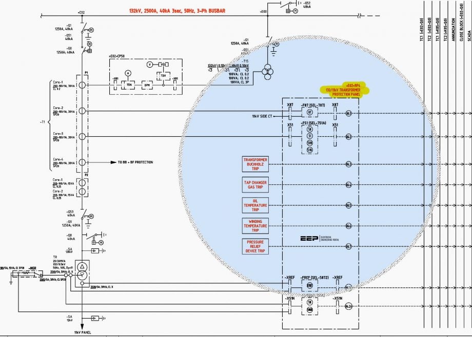
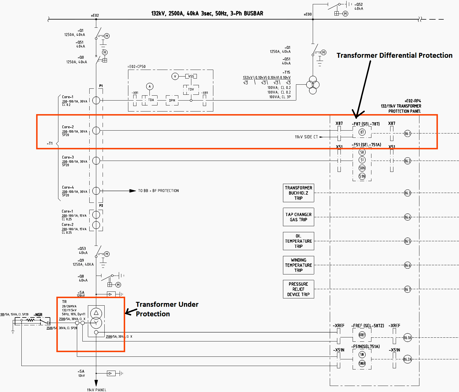
Please refer to Figure 2, which illustrates the relay’s placement in the diagram for a power transformer. In this diagram, you can observe that the differential relay is connected to the CTs at the switchgear side, providing protection not only for the transformer windings but also for the bushings, cables, conductors, and a portion of the switchgear before the CT core.
It’s important to note that this transformer is equipped with one differential protection, HV and LV overcurrent protection, restricted earth fault protection, and neutral or Neutral Grounding Resistor (NGR) overcurrent protection.
Figure 2 – Relay and metering diagram of the power transformer
3. Restricted Earth Fault Protection (REF)
Restricted Earth Fault (REF) protection functions as a specialized form of Differential Protection, with the primary distinction lying in its heightened sensitivity compared to standard Differential Protection schemes. To understand the concept of REF Protection, let’s consider a transformer with a DYn configuration, where the high-voltage (HV) side of the transformer is Delta-connected, the low-voltage (LV) side is Star-connected, and the neutral point is solidly grounded.
In this setup, there are four Current Transformers (CTs) involved: three CTs connected to each phase (R, Y, and B) and one CT connected to the neutral. The secondary windings of these four CTs are interconnected in parallel, and this parallel arrangement is subsequently linked to the REF Relay Coil.
During normal, balanced operating conditions, the sum of currents through the secondary windings of the CTs should equate to zero, and the current in the neutral CT should also be zero. However, when a fault occurs in the secondary winding of the transformer, the currents in the R, Y, and B phases will cease to be balanced.
It’s essential to understand that for faults occurring outside the transformer, such as through faults, the Restricted Earth Fault Protection does not come into operation. This is due to the fact that, in the case of through faults, the vector sum of three-phase currents called 3Io & neutral CT current IN will indeed amount to zero.
Consequently, this protection scheme is specifically tailored for safeguarding a limited or “restricted” zone, hence its name, Restricted Earth Fault Protection.
Related electrical guides & articles


Muhammad Kashif
Muhammad Kashif Shamshad is an Electrical Engineer and has more than 17 years of experience in operation & maintenance, erection, testing project management, consultancy, supervision, and commissioning of Power Plant, GIS, and AIS high voltage substations ranging up to 500 kV HVAC & ±660kV HVDC more than ten years experience is with Siemens Saudi Arabia.Profile: Muhammad Kashif
