
Estimated Study Time: 7 minutes
Standby generators
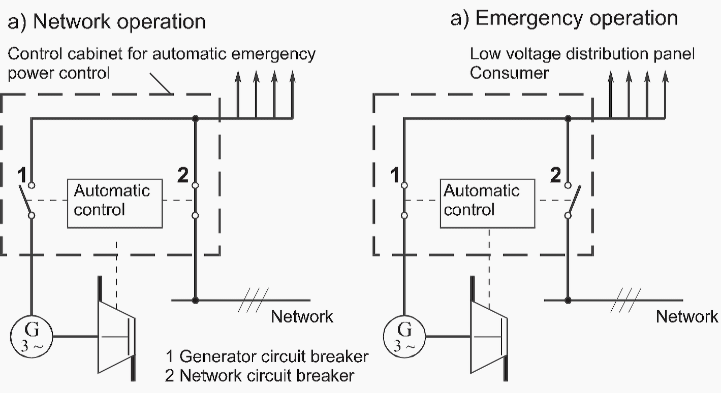
Standby generators are used in order to provide consumers in the system entitled to standby service in the event of breakdown or shutdown of the normal power supply. They consist of the generator, the flywheel and the motor.
 How standby generators work and how to dimension them? (on photo: Standby Generator Installation For Parallel Operation; credit: tgc.uk.com)
For the dimensioning of the generator power to supply a large number of consumers, the connected load with the coincidence factor must be taken as the basis.
This connected load should be about 60 % of the rated load for the standby generator. The prime mover must be designed for the effective power and the generator for the apparent power. The feed-in of the network to the automatic standby power control takes place through the secondary distribution, to which other consumers are also connected.
The functional and operational reliability of standby generators is ensured only when the planning takes account of all requirements for channeling air intake and exhaust air, room ventilation, sound attenuation and fuel supply!
The main components are:
- Generator
- Battery system
- Emergency standby control
- Fuel system
- Exhaust system with sound attenuation
- Fans for room ventilation
- Air intake and exhaust ducts
The starting power (Figure 2) and the correction factor (Figure 3) for consumers with a high starting power, taking into account the still permissible voltage dip, are calculated as follows and an additional 20 % reserve is planned to cover future energy requirements.


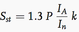
The starting power:
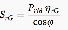
Generator power:
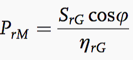
Motor drive power:
The meanings of the symbols in above formulas are:
- IA – Starting current in A
- Sst – Consumer starting power in kVA
- In – Rated current in A
- k – Correction factor for operating conditions
- P – Effective power in kW
- PrM – Motor drive power in kW
- SrG – Generator power in kVA
- cosφ – P Power factor
Generator specific limiting operational values
Application // Communal facilities
After a switching time of maximum 15 seconds, 100% of the consumer power for the required safety equipment must be supplied (Table 1).
Table 1 – Electrical installations in hospitals and communal facilities
| Characteristic parameter | Communal facilities | In hospitals |
| Static frequency deviation | 5% | 4% |
| Dynamic frequency deviation | ± 10% | ± 10% |
| Frequency adjustment time | 5 s | 5 s |
| Static voltage deviation | ± 2.5% | ± 1% |
| Dynamic voltage deviation | ± 20% | ± 10% |
| Voltage adjustment time | 4 s | 4 s |
| Steady state short circuit current | 3×In (3 s) | 3×In (3 s) |
| Total harmonic distortion of voltage | 3 ∼ < 5% | 3 ∼ and 1 ∼ < 5% |
Application // Electrical installations in hospitals
After a switching time of maximum 15 seconds, 80 % of the consumer power (consumers of the required safety equipment and operationally important consumers) in a maximum of two steps and after a further 5 seconds 100 % of the total consumer power must be supplied (Table 1 above). For inductive consumers the large starting current must also be considered (Table 2 below).
Table 2 – Standard values for starting currents
| Startup procedure | IA/IrM |
| Direct startup | 4 … 6 |
| Squirrel cage rotor via star delta | 2 … 3 |
| Squirrel cage rotor via frequency converter | 1.5 … 3 |
| Squirrel cage rotor via phase control | 2 … 4 |
Type classes 2 and 3 – Connecting and disconnecting loads takes place in accordance with the regulations
Table 3 – Type class 2 and 3
| Characteristic parameter | Class 2 | Class 3 |
| Static frequency deviation | 5% | 3% |
| Dynamic frequency deviation | ± 10% | ± 7% |
| Frequency adjustment time | 5 s | 3 s |
| Static voltage deviation | ± 1% | 1% |
| Dynamic voltage deviation | + 22%; – 18% | + 20%; – 15% |
| Voltage adjustment time | 6 s | 4 s |
| Steady state short circuit current | 3×In (3 s) | 3×In (3 s) |
| Total harmonic distortion of voltage | 3 ∼ < 5% | 3 ∼ < 5% |
Planning a standby generator
The following features must be considered during the planning of standby generators:
- Characteristic parameters of the network, such as type and number of active conductors of the feed-in, type of ground connections (mostly TN-S systems)
- Determination of the power requirements with the coincidence factor
- Expected three-pole and single-pole short circuit currents at the feed-in point
- Distribution of phase loads for the operational equipment of the electrical system
- Switching between network and standby power with mutual mechanical or electrical locking
- Connection of the standby generator to the existing network takes place up to 125 A through a 5-pin CEE plug-and-socket device with HO7RN-F line.
- System ground can be in the form of a concrete footing electrode, ring conductor or buried grounding electrode.

Example – Calculation of standby generator power
The following data are known for a three-phase motor:
- Speed = 1480 rpm
- Rated power = 22 kW
- Rated current = 42 A
- Power factor cosφ = 0.88
- Starting current direct: factor 5.5
- Starting current star-delta: factor 2.3
- Voltage dip 15 % in accordance with communal facility regulations
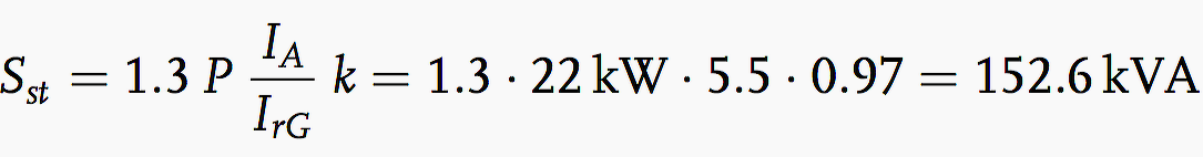
For the correction factor k, from Figure 3 we find a value of 0.97. Starting power with direct startup:
Starting power with star delta connection:

For 15 % voltage dip, from Figure 2 we find a factor of 1.25. The required standby power for the delta connection is:

and for the Y/Δ connection:

Cummins emergency generator training (VIDEO)
Training video on a Cummins, natural gas, emergency generator.
Onsite generator training (VIDEO)
How to use a Caterpillar XQ 30 diesel generator (VIDEO)
At Portland,OR’s Peterson Cat, Hil learned about how to use Caterpillar XQ diesel generator series. Cost of a used XQ 20 was ~$13,000.
Reference // Analysis and design of low voltage power systems by Ismail Kasikci (Get hardcopy from Amazon)
Related electrical guides & articles


Edvard Csanyi
Hi, I'm an electrical engineer, programmer and founder of EEP - Electrical Engineering Portal. I worked twelve years at Schneider Electric in the position of technical support for low- and medium-voltage projects and the design of busbar trunking systems.I'm highly specialized in the design of LV/MV switchgear and low-voltage, high-power busbar trunking (<6300A) in substations, commercial buildings and industry facilities. I'm also a professional in AutoCAD programming.
Profile: Edvard Csanyi

how could you find the value k=0.97 of the correction factor ?