
Estimated Study Time: 8 minutes
Turbines and diesel engines
The main types of prime movers used in engine driven generator sets for industrial sites and commercial buildings are Diesel engines, gas turbines, and steam turbines. Turbines are used mainly for production sets whereas Diesel engines can be used for both production and standby sets.
 Typical power supply schemes for standby and production generator sets
Topics covered in this article are not dependant on the type of prime mover used, and therefore the general term generator set will be used. The choice of the prime mover is determined by such considerations as the availability and type of fuel and is not covered in this technical article.
Since Diesel engines are very often used some specific information about Diesel generator sets will be given.
Standby generator sets
The typical supply of essential loads for commercial buildings, small industrial sites or for emergency power to unit substations in a larger site, is shown in Figure 1.
Under normal operating conditions the essential load is supplied from the utility supply. Upon loss of this supply the bus-tie circuit breaker Q3 is tripped, the generator set is started, and then load is supplied by the standby generator set by closing the generator circuit breaker Q2.
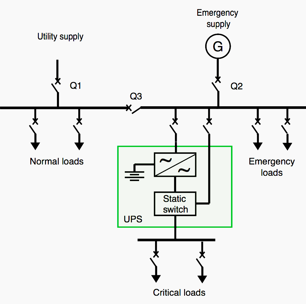
Critical loads which cannot accept any power outage are supplied by the UPS. The UPS is equipped with a static switch which will immediately bypass the rectifier/inverter module in case of an internal fault and thus ensure a continuous supply of electrical power.
Both the normal and the backup supply to the UPS should be taken from the essential busbar.
For large industrial sites a centralized emergency power supply system as shown in Figure 2 is often used. The main emergency switchboard is normally supplied from the utility, although in some sites one of the generator sets may be in constant operation.
The emergency switchboard is designed to allow generator sets to operate in parallel and also to be connected to the utility supply.
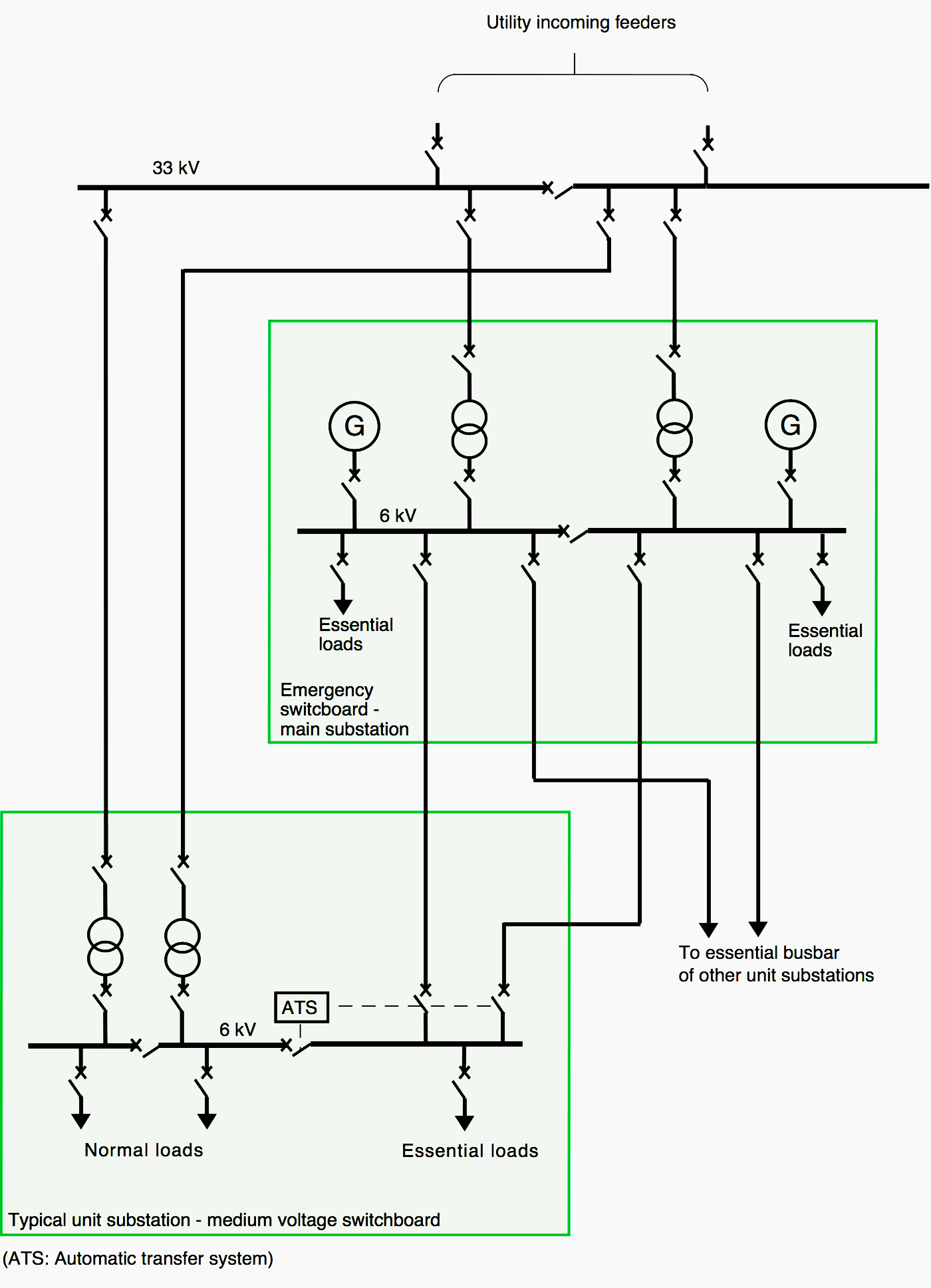
The automatic transfer from the utility to the emergency supply is performed in each unit substation. Since the emergency switchboard is normally energized, fast transfers without loss of plant load can be used.
The use of a centralized emergency supply has the following advantages:
- fewer generator sets for the site (normally maximum of 2),
- permanently energized emergency supply allowing fast transfer schemes to be used,
- no loss of emergency supply due to maintenance of one generator set.
Generator sets for such systems are normally in the 1-4 MW range.
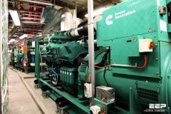
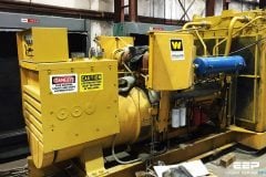
Load testing a 500kVA generator
2. Production generator sets
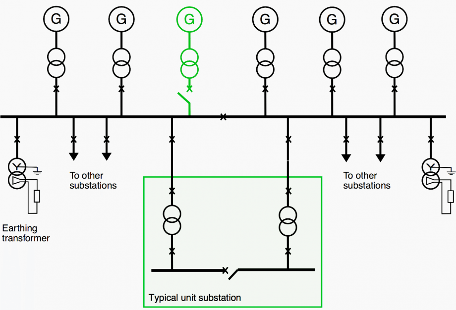
For remote sites having no utility supply, several generator sets are used. A typical distribution system is shown in Figure 3.
The generator set size should be such that they are loaded at least 50%. A poor load factor can be detrimental to the sets. For example, Diesel engines loaded at less than 30% will not achieve a good operating temperature resulting in poor combustion and degrading of lubrication oil.
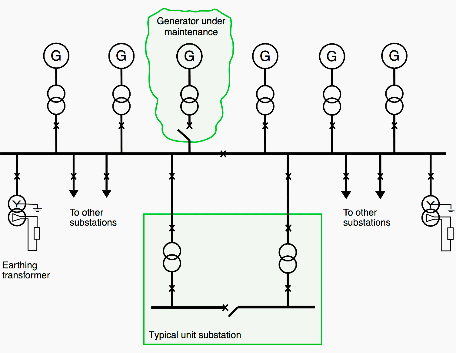
Plant operation at N – 2 sets should also be considered, this case occurring when one set is being maintained and there is a loss of an additional set. The highest initial load factor F that can be used with N installed generators such that load shedding is not required for N – 2 operation can be determined from:
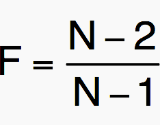
For example the highest load factor for N = 6 will be 80%. Bus-tie circuit breakers are often used for maintenance purposes. During normal plant operation all bus-tie circuit breakers are normally closed. Short-circuit calculations should always take operation with N generators into account since it is normal to connect standby sets prior to switching off sets for maintenance.
Determination of how much load must be shed requires dynamic simulation of the network for different fault conditions such as a loss of a generator or a short-circuit. Prior to the study it is necessary to determine which operating configurations are to be considered.
Operating conditions with the bus-tie circuit breaker both in the open and the closed positions will greatly increase the complexity of the load shedding system since each busbar can be operated independently and will require specific load shedding criteria. For most plants it is recommended that only the standard operating configuration be used for the dynamic simulations and definition of the load shedding strategy.
Figure 3 shows each generator having its own transformer. The use of generator transformers has several advantages:
- Provides flexibility in the choice of generator voltage,
- Reduces peak short-circuit current at main board,
- Allows use of high impedance generator grounding (reduces possible damage to generator).
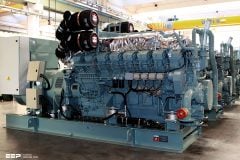
1 megawatt turbine natural-gas powered generator
Reference // Integration of local power generation in industrial sites and commercial buildings by T. Hazel (Schneider Electric)
Related electrical guides & articles


Edvard Csanyi
Hi, I'm an electrical engineer, programmer and founder of EEP - Electrical Engineering Portal. I worked twelve years at Schneider Electric in the position of technical support for low- and medium-voltage projects and the design of busbar trunking systems.I'm highly specialized in the design of LV/MV switchgear and low-voltage, high-power busbar trunking (<6300A) in substations, commercial buildings and industry facilities. I'm also a professional in AutoCAD programming.
Profile: Edvard Csanyi

Thank’s to share, you’re material very helpful.
Good Info
Thanks Very Useful Information.
Very good article. Information about emergency and special sources always are important.
Muy buen material, bien esquematizado y muy buenos videos ,gracias.
Thanks so much. Keep it up for me
very informative article… NOW I KNOW..
keep it up guys.
hi, keep up it up. you material provides information
thanks.