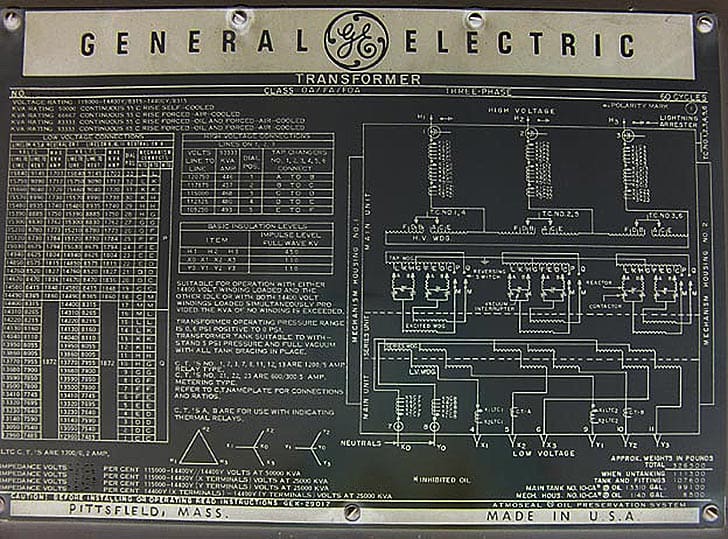
Star-Delta Connection Overview
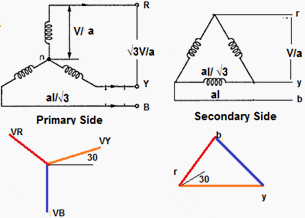
In this type of transformer connection, then primary is connected in star fashion while the secondary is connected in delta fashion as shown in the Figure 1 below.
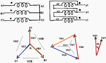
The voltages on primary and secondary sides can be represented on the phasor diagram as shown in the Figure 2 below.
Key points
- As Primary in Star connected
- Line voltage on Primary side = √3 X Phase voltage on Primary side. So
- Phase voltage on Primary side = Line voltage on Primary side / √3
- Now Transformation Ration (K) = Secondary Phase Voltage / Primary Phase Voltage
- Secondary Phase Voltage = K X Primary Phase Voltage.
- As Secondary in delta connected:
- Line voltage on Secondary side = Phase voltage on Secondary side.
- Secondary Phase Voltage = K X Primary Phase Voltage. =K X (Line voltage on Primary side / √3)
- Secondary Phase Voltage = (K/√3 ) X Line voltage on Primary side.
- There is s +30 Degree or -30 Degree Phase Shift between Secondary Phase Voltage to Primary Phase Voltage
Advantages of Star Delta Connection
- The primary side is star connected. Hence fewer numbers of turns are required. This makes the connection economical for large high voltage step down power transformers.
- The neutral available on the primary can be earthed to avoid distortion.
- The neutral point allows both types of loads (single phase or three phases) to be met.
- Large unbalanced loads can be handled satisfactory.
- The Y-D connection has no problem with third harmonic components due to circulating currents inD. It is also more stable to unbalanced loads since the D partially redistributes any imbalance that occurs.
- The delta connected winding carries third harmonic current due to which potential of neutral point is stabilized. Some saving in cost of insulation is achieved if HV side is star connected. But in practice the HV side is normally connected in delta so that the three phase loads like motors and single phase loads like lighting loads can be supplied by LV side using three phase four wire system.
- As Grounding Transformer: In Power System Mostly grounded Y- ∆ transformer is used for no other purpose than to provide a good ground source in ungrounded Delta system. Take, for example, a distribution system supplied by ∆ connected (i.e., ungrounded) power source.
.
If it is required to connect phase-to-ground loads to this system a grounding bank is connected to the system, as shown in Figure 3 below:
Figure 3 – Y-D Grounding transformer - This system a grounding bank is connected to the system, as shown in Figure 3. Note that the connected winding is not connected to any external circuit in Figure 3.
- With a load current equal to 3 times i, each phase of the grounded Y winding provides the same current i, with the -connected secondary winding of the grounding bank providing the ampere-turns required to cancel the ampere-turns of the primary winding. Note that the grounding bank does not supply any real power to the load; it is there merely to provide a ground path. All the power required by the load is supplied by two phases of the ungrounded supply.
Disadvantages of Star-Delta Connection
In this type of connection, the secondary voltage is not in phase with the primary. Hence it is not possible to operate this connection in parallel with star-star or delta-delta connected transformer.
One problem associated with this connection is that the secondary voltage is shifted by 300 with respect to the primary voltage. This can cause problems when paralleling 3-phase transformers since transformers secondary voltages must be in-phase to be paralleled. Therefore, we must pay attention to these shifts.
If secondary of this transformer should be paralleled with secondary of another transformer without phase shift, there would be a problem.
Application
It is commonly employed for power supply transformers. This type of connection is commonly employed at the substation end of the transmission line. The main use with this connection is to step down the voltage. The neutral available on the primary side is grounded. It can be seen that there is phase difference of 30° between primary and secondary line voltages.
Commonly used in a step-down transformer, Y connection on the HV side reduces insulation costs the neutral point on the HV side can be grounded, stable with respect to unbalanced loads. As for example, at the end of a transmission line. The neutral of the primary winding is earthed.
In this system, line voltage ratio is 1/√3 Times of transformer turn-ratio and secondary voltage lags behind primary voltage by 30°. Also third harmonic currents flow in the to give a sinusoidal flux.





Transformer rating 1500kva
Primary volt 800V connected instar and secondary volt 11kv connected in delta, percentage impedance is 4 ohm. Then please calculate the fault current…
I guess figure 1 has some mistake like V/a, it should be just V, should it not ?
I am using Star / Delta (Yd11) transformer along with Load balancing unit for heater application. I need clarification / guidance about in primary of transformer will be provided winding for neutral or it will directly (separately) earth.
Are delta connected transformer applicable in low voltage distribution?
Why phase to phase short do not occur in delta point in transformers while they are out of phase. But in case of LT/HT line phase to phase short occurs.
I need a 10 – 15 kva 3 phase distribution transformer that can provide 120 volts power to appliances from a power system that provides 240 volts line to neutral.
What kind of primary and secondary winding would be suitable, Y-Y, D-Y, D-D, or Y-D ?
I’d very much appreciate your expertise.
Allan Atsu
How the secondary side of the transformer and it’s bus is protected in Star delta type transformer.
Pl explain in details
good
Dear Er. Jignesh,
When we use star delta step down TR( like in SVC- 220/25KV), assume that no grounding TR is used. In that case the ground stabilaization of LV winding is possible only through the neutral point of the LV -VT.
Is it adequate to mitigate capacitive coupled votage rise of the LV winding with reference to ground?
Or a static shielded TR LV is required? Is their any risk of HV to LV capacitance resonating with VT primary impedence? Mohanan Nair, Senior Engineer, NG, KSA
how to measure the impedance of three winding transformer we have 1.5kva 11000v /320-320v transformer three winding please solve my problem. thank you.
I have a power transformer grounding on the primary y side. The relay feeding this section of the network is showing current looks to ground. The TX is presently very lightly loaded. Is this earth current to be expected
what is difference between line turn ration and phase turn ratio of three phase transformer.
Key Point 10 should be modified as following:
10. There is s +30 Degree or -30 Degree Phase Shift between Secondary Phase(line) Voltage to Primary line Voltage
We have Star Delta power transformer and there is neutral current flowing in circuit though neutral is earthed. This current also changes , Please advise the reason or it will be there ,so what should be the earth fault current setting in this case.
I want advantge and disadvantage of two delta one star single phase step up genration transformer and one delta one star single phase step up generation transformer. I want a bright response from you
Thanks
how the start earthing transformer designe.plz send the excel work sheet on my mail
What is the voltage ratio of
Yzn11, Zigzag, 100 kVA, 20000/400 V transformer…please clarify
building has 120/208 volts 3phase I need to hookup a 3phase 460 volts for a condenser unit on a rooftop stepup transformer do I install the neutral on the primary side of the transformer what about the secondary delta side 460 volts ? what if their is a fault on the secondary side short circuit how will the OCP device open ? transformer will be grounded as per NEC if their should be a ground fault . could I ground the neutral and equipment to the same ground on the frame ground terminal ? thanks for any input.
What is the insulation resistance result of 630KVA transformer at HT & LT Side between each phase ?
Kindly send me the results (out put voltage) , when one phase of three phase transformer is not given (say R phase) and R phase winding is shorted in delta side of delta – star transformer. I require the magnitude of out put voltages on star side.The transformer rating is 11KV/433V, 100 KVA, Delta-Star transformer.
Please show the diagram in which a power generation , transmission and distribution system is shown with transformer connected, type of transformer and windings must be clearly vißible .last time there was a stion in exam
Q. In a transmission system,the stàr side of stardelta transformer is on the HV side, whereas in a distribition system, the star side is on the low voltage side. Explain,. Please provide the ans with appriate explanation
please whats the relation between the secondary and primary line voltages
With all due respect, there are some over simplifications in the text, such as under “Disadvantages” it is basically the same disadvantage mentioned three times, and it appears as if only transformers with a WINDING ratio of 1:1 can be treated this way.
Would you be so kind as to rewrite your article as DELTA-STAR. Using the primary as the DELTA and H1, H2, H3 as the terminals.
The secondary as the STAR and X1, X2, X3 as the terminals.
Thus the transformer name plate will match your discussion.
Thanks, Tom Zazulak
no offence but this article is not clear at all…..