
Estimated Study Time: 30 minutes
From dumb to intelligent motor start
The AC induction motor is a key component of the modern world economy. These motors are used in industrial facilities all over the world to power the equipment that boosts productivity and efficiency. However, during motor start-up, many industrial activities unwittingly put their machinery under extreme stress.
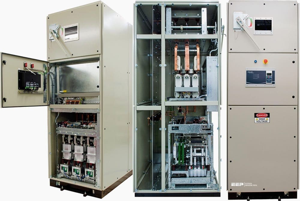
 Six different ways to start a medium-voltage motor you should know about (on photo: LV cabinet of a medium voltage motor control starter type Ampgard, Eaton)
High inrush currents enter into the motor’s windings as motor operation is initiated, providing extremely high amounts of torque.
It’s worth noting that VSDs can result in significant energy savings since many pump and fan systems operate at less than full capacity for a large portion of the time and even a little drop in speed can have a significant impact on energy usage.
Even while motor efficiency has increased by an average of 3-4% over the past twenty years, this is especially true when compared to motors that are constantly running at full speed.
Ok, let’s discuss now the following motor starting methods, their current, torque profile and installation schematics.
- Direct on-line starting
- Primary resistance starting
- Auto-transformer starting
- Star-Delta starting
- Soft starters
- Variable frequency drives (VFD)
- BONUS! Motor Control Seminar Notes (PDF)
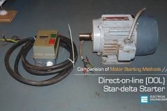
1. Direct On-Line Motor Starting (DOL)
The simplest form of starter is the direct on-line (DOL) starter, consisting of an isolation contactor and motor overload protection device. DOL starters are extensively used in some industries, but in many cases full voltage starting is not permitted by the power authority.
Medium voltage DOL control supports a wide range of industrial applications including water and wastewater, pulp and paper, oil and gas and HVAC.
Full voltage starting causes a current transition from zero to locked rotor current (LRC) at the instant of contactor closure. LRC is typically between five and ten times motor FLC. The fast rising current transient induces a voltage transient in the supply, and causes a voltage deflection of six to nine times that expected under full load conditions.
Figure 1 – Current and torque profile for DOL starting

Where the curve numbers mean:
- Full voltage motor current
- Full voltage motor torque
- Load torque (quadratic load, eg pump)
The damage resulting from the torque transient is more severe than that due to the maximum torque amplitude.
Figure 2 – DOL starter installation

Where:
- Main contactor
- Overload relay
Figure 3 – How it looks like: Full voltage (direct-on-line) motor started

Go back to the Contents Table ↑
1.1 Disadvantages of classic DOL starting
- High inrush currents create stress on the motor’s windings. This stress will cause the windings to move in the end turns of the stator. This will cause the insulation to break down. Eventually, phase to phase shorts will occur and result in early motor failure.
- Full voltage starting will cause damage to belts, sheaves, gearboxes, and other mechanical components throughout the application drive train, thus causing downtime and replacement costs.For the most part, it is the down time that proves to be the most costly motor control method in any industry.
- Full voltage starting can create line drops/voltage dips which may result in penalties from the utility company. The line drops that large motors can create may also cause problems with other applications throughout the plant.
- Across The Line starting puts large amounts of stress on the contactor contacts which, in turn, require a relatively large amount of maintenance.
- Poor motor protection with the use of overload with 20% accuracy.
- No capability to control the deceleration.
Go back to the Contents Table ↑
2. Primary Resistance Motor Starting
Primary resistance starters use resistors connected in series with each phase, between the isolation contactor and the motor, which limit the start current and torque. The resistors may be wound, cast or liquid resistors.
The motor current is equal to the line current and the starting torque is reduced by the square of the current reduction ratio. The current reduction depends on the ratio of the motor impedance to the sum of the added primary resistance and motor impedance.
If the resistors are too high in value, there will be insufficient torque to accelerate the motor to full speed, so the step to full voltage will result in a high current and torque step!
Figure 4 – Primary resistance starter

Where:
- Main contactor
- Run contactor
- Start resistors
- Overload relay
The reduced voltage start time is controlled by a preset timer which must be correctly set for the application. If the time is too short, the motor will not reach full speed before the resistors are bridged. Excessive start time results in unnecessary motor and resistor heating.
Several stages of resistance can be used and bridged in steps to control the current and torque more accurately. This minimises the magnitude of the current and torque steps.
Primary resistance starters are closed transition starters, so they are not subject to ‘reclose’ transients.
Figure 5 – Start performance characteristics of a correctly selected primary resistance starter

Where the curve numbers mean:
- Full voltage start current
- Primary resistance start current
- Full voltage torque
- Primary resistance torque
- Load torque
Figure 6 – Start performance characteristics of an incorrectly selected primary resistance starter

Where the curve numbers mean:
- Full voltage start current
- Primary resistance start current
- Full voltage torque
- Primary resistance torque
- Stall point
- Current and torque transient
Go back to the Contents Table ↑
2.1 How does soft start compare to classic primary resistance starting?
Compared with primary resistance starters, soft starters are more flexible and reliable. Primary resistance starters offer limited performance because:
- Start torque cannot be fine-tuned to match motor and load characteristics.
- Current and torque transients occur at each voltage step.
- They are large and expensive.
- Liquid resistance versions require frequent maintenance.
- Start performance changes as the resistance heats up, so multiple or restart situation are not well controlled.
- They cannot accommodate changing load conditions (eg loaded or unloaded starts).
- They cannot provide soft stop
2.2 Reduced-Voltage Solid-State (RVSS) Starters
Reduced-voltage solid-state starters limit the starting current as the voltage is scaled up to the motor to produce smooth acceleration. When the motor has reached its maximum speed, the bypass contactor closes, providing the motor with its full voltage.
Similar to reactor and autotransformer starters, which lower starting torque, RVSS technology may adjust the start and ramp settings. Making ensuring the motor can start the load under low torque conditions is crucial.
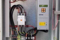
Figure 7 – How it looks like: Reduced-Voltage Solid-State (RVSS) Starter

Why is Reduced-Voltage Solid-State (RVSS) “Soft” Starting Desirable?
- Eliminate shock to your mechanical components
- Avoid coupling and shaft damage
- Prevent rotor and winding failure
- Stop drive belt squeal and breakage
- Prevent water hammer in pipes
- Soft stop the pump motors
- Reduce pressure so valves close gently
- Avoid the surge wave
- Reduce peak starting currents
- Reduce voltage drop on motor start
Go back to the Contents Table ↑
3. Auto-Transformer Motor Starting
Auto-transformer starters use an auto-transformer to reduce the voltage during the start period. The transformer has a range of output voltage taps which can be used to set the start voltage, and the start time is controlled by a timer. The motor current is reduced by the start voltage reduction, and further reduced by the transformer action resulting in a line current less than the actual motor current.
The initial line current is equal to the Locked Rotor Current (LRC) reduced by the square of the voltage reduction. A motor started on the fifty percent tap of an auto-transformer will have a line start current of one quarter of LRC and a start torque of one quarter of Locked Rotor Torque (LRT).
If the start voltage is too low, or the start time is too short, the transition to full voltage will occur with the motor at less than full speed, resulting in a high current and torque step.
Figure 8 – Auto-transformer connection

Where:
- Run contactor
- Thermal overload
- Start contactor (A)
- Auto-transformer
- Start contactor (B)
The simplest auto-transformer starters are single step and often control two phases only. More sophisticated starters may step through two or more voltage steps while accelerating from the initial start tap to full voltage.
Reduced voltage soft starting of induction motors is accomplished using the Korndorfer starter technique. A three-phase autotransformer and three three-phase switches are used in the circuit.
Figure 9 – Start performance characteristics of a correctly selected auto-transformer starter
Where the curve numbers mean:
- Full voltage start current
- Auto-transformer start current
- Full voltage torque
- Auto-transformer torque
- Load torque
Figure 10 – Start performance characteristics of an incorrectly selected auto-transformer starter

Where the curve numbers mean:
- Full voltage start current
- Auto-transformer start current
- Full voltage torque
- Auto-transformer torque
- Stall point
- Current and torque transient
Figure 11 – How it looks like: Auto-Transformer Motor Starting

Go back to the Contents Table ↑
3.1 How does soft start compare to auto-transformer starting?
Compared with auto-transformer starters, soft starters are much more flexible and provide a much smoother start. Auto-transformer starters offer limited performance because:
- They offer only limited ability to adjust start torque to accommodate motor and load characteristics.
- There are still current and torque transients associated with steps between voltages.
- They are large and expensive.
- They are especially expensive if high start frequency is required.
- They cannot accommodate changing load conditions (eg. loaded or unloaded starts).
- They cannot provide soft stop.
Go back to the Contents Table ↑
4. Star-Delta Motor Starting
Star-delta starters are the most common reduced voltage starter used in industry because of their low cost. The motor is initially connected in star configuration, then after a preset time the motor is disconnected from the supply and reconnected in delta configuration.
The current and torque in the star configuration are one third of the full voltage current and torque when the motor is connected in delta.
Figure 12 – Star/delta motor starter installation

Where:
- Main contactor
- Thermal overload
- Motor (three-phase)
- Delta contactor
- Star contactor
The star and delta configurations provide fixed levels of current and torque, and cannot be adjusted to suit the application.
If the star configuration does not provide enough torque to accelerate the load to full speed, a high starting torque motor such as a double cage motor should be employed. If the motor does not reach full speed in star, the transition to delta configuration will result in a high current and torque step, defeating the purpose of reduced voltage starting.
The closed transition starter reduces the ‘reclose’ effect but does not improve the controllability of the start parameters.
Figure 13 – Start performance characteristics of a star/delta motor starter

Where the curve numbers mean:
- Full voltage start current
- Star-delta start current
- Full voltage torque
- Star-delta torque
- Stall point
- Current and torque transient
Go back to the Contents Table ↑
4.1 How does VFD and soft start compare with star/delta starting?
Compared with star/delta starters, soft starters and VFDs are much more flexible and provide a smooth start with no risk of transients. Star/delta starters offer limited performance because:
- Start torque cannot be adjusted to accommodate motor and load characteristics.
- There is an open transition between star and delta connection that results in damaging torque and current transients.
- They cannot accommodate varying load conditions (eg. loaded or unloaded starts).
- They cannot provide soft stop.
The main advantages of star/delta starters are:
- They may be cheaper than a soft starter and VFD.
- When used to start an extremely light load, they may limit the start current to a lower level than a soft starter or VFD. However, severe current and torque transients may still occur.
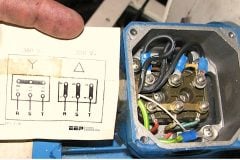
In the Delta pattern, all of the windings are connected phase-to-phase in series, just as they would be in a standard motor.
In the “Y” configuration, each set of phase windings is brought together at a common point. This increases the impedance of the motor itself, reducing the current and torque to 33% of normal. Three contactors and a timer are used to switch the six leads brought out of the motor into the Y-then-Delta configuration in a two-step starting process.
Suggested Video – Wye-Delta Motor Starter
Go back to the Contents Table ↑
5. Medium-Voltage Soft Starters
Electronic soft starters control the voltage applied to the motor by means of an impedance in series with each phase connected to the motor. The impedance is provided by AC switches – reverse parallel connected SCR-diode or SCR-SCR circuits. The voltage is controlled by varying the conduction angle of the SCRs.
The SCR-SCR switch is a symmetric controller, which results in odd order harmonic generation. The SCR-diode switch is an asymmetric controller, which causes even order harmonic currents to flow in the motor and supply. Even order harmonics are undesirable for motor control because of the increased losses and heating induced in the motor and supply transformers.
Figure 14 – Soft starter motor control

Where:
- Main contactor
- Electronic soft starter
- Overload relay
Electronic soft starters come in two control formats:
1. Open loop controllers: which follow a timed sequence. The most common open loop system is timed voltage ramp, where the voltage begins at a preset start voltage and increases to line voltage at a preset ramp rate.
2. Closed loop controllers: which monitor one or more parameters during the start period and modify the motor voltage in a manner to control the starting characteristics. Common closed loop approaches are constant current and current ramp.
Figure 15 – Medium voltage soft starter for heavy-duty motor control
Suggested Video – Motortronics Medium Voltage Soft Starter Test
Suggested Video – AuCom/Benshaw, motor starting with softstarter
Go back to the Contents Table ↑
6. Variable Frequency Drives (VFD)
A variable frequency drive (VFD) converts AC (50 or 60 Hz) to DC, then converts the DC back to AC, with a variable output frequency of 0-250 Hz. The running speed of a motor depends on the supply frequency, so controlling the frequency makes it possible to control the speed of the motor.
A VFD can control the speed of the motor during starting, running and stopping.
VFDs generate significant emissions and harmonics, and a filter is generally required. VFDs are also called variable speed drives (VSD) or frequency converters.
Drives perform the functional rectification of the primary AC power source and convert DC to variable frequency AC. With starting currents that aren’t any higher than running currents, the motor accelerates smoothly.
Additionally, starting torque is unaltered, allapping worries about having enough torque to accelerate.
Figure 16 – How MV VFD looks like: Eaton’s SC9000 EP MV variable frequency drive

Go back to the Contents Table ↑
6.1 VFD motor starting
When a VFD starts a motor, it initially applies a low frequency and voltage to the motor. The starting frequency is typically 2 Hz or less. This avoids the high inrush current that occurs when a motor is started DOL. The VFD increases the frequency and voltage at a controlled rate to accelerate the load without drawing excessive current.
It’s worth noting that:
- The current on the motor side is in direct proportion to the torque that is generated
- The voltage on the motor is in direct proportion to the actual speed
- The voltage on the network side is constant
- The current on the network side is in direct proportion to the power drawn by the motor
VFDs are ideal for applications with an extremely limited supply because the starting current is never more than the motor FLC.
Suggested Course – Practical Course to Wiring and Setting Parameters of VFDs
Practical Course to Wiring and Setting Parameters of Variable Frequency Drives (VFDs)
Go back to the Contents Table ↑
6.2 VFD motor stopping
The stopping sequence is the opposite of the starting sequence. The frequency and voltage applied to the motor are ramped down at a controlled rate. When the frequency approaches zero, the motor is shut off. A small amount of braking torque is available to help slow the load, and additional braking torque can be obtained by adding a braking circuit.
With 4-quadrants rectifiers (active-front-end), the VFD is able to brake the load by applying a reverse torque and returning the energy to the network.
The precise speed control available from a VFD is useful for avoiding water hammering in pipe systems, or for gently starting and stopping conveyor belts carrying fragile material.
Suggested Reading – Inside Variable Frequency Drive (VFD) Panel: Configuration, Schematics and Troubleshooting
Inside Variable Frequency Drive (VFD) Panel: Configuration, Schematics and Troubleshooting
Go back to the Contents Table ↑
6.3 VFD motor running
The ability to control motor speed is a big advantage if there is a need for speed regulation during continuous running. If the application only requires an extended starting and/or stopping time, a VFD may be more expensive than necessary.
Running at low speeds for long periods (even with rated torque) risks overheating the motor. If extended low speed/high torque operation is required, an external fan is usually needed. The manufacturer of the motor and/or the VFD should specify the cooling requirements for this mode of operation.
Suggested Guide – Installation guidelines for AC power drive systems (VSDs and motors)
Installation guidelines for AC power drive systems (VSDs and motors)
Go back to the Contents Table ↑
6.4 VFD bypassed
In some medium voltage motor applications, a VFD is used to start the motor but is bypassed by a contactor or circuit breaker when running at mains supply frequency. This means that:
- The motor start current never exceeds the motor full load current. This is very useful on sites where the mains supply capacity is limited.
- The overall motor control system is more reliable because the VFD is only required during starting and stopping.
- If the VFD malfunctions, the motor can still be started and run DOL, via the bypass switch. In this case, the mains supply must have the capacity to start the motor.
Control of the bypass switch can be automatic or manual.
[highlight22]Figure 17[/highlight2] – Bypassed VFD installation

Where:
- 1 – Three-phase supply
- 2 – VFD
- 3 – Motor
- K1A – VFD input contactor
- K1B – VFD output contactor
- K2 – Bypass contactor
- F1-3 – Fuses
- PR – Motor protection relay
Operation sequence:
- Contactors K1A and K1B close and the motor is run up to full speed. Once the output of the VFD reaches main supply frequency, contactors K1A and K1B open. After a short delay, bypass contactor K2 closes.
- Contactors K1B and K2 are electrically and mechanically interlocked. The VFD can be isolated from operation by racking out contactors K1A and K1B.
- Motor protection relay PR protects the motor when K2 is closed.
Suggested Reading – Learn how to listen and read the motor’s soul
Never let an electric motor drop dead. Learn how to listen and read the motor’s soul.
Go back to the Contents Table ↑
7. BONUS! Motor Control Seminar Notes (PDF)
Download Motor Control Seminar notes in PDF format (for premium members only):
Sources:
- MV application guide for engineers to select and specify the right MV equipment by Aucom
- 7.2 kV motor control (Ampgard) medium-voltage, non-arc resistant by Eaton
- SC9000 EP medium-voltage variable frequency drive by Eaton
Related electrical guides & articles


Edvard Csanyi
Hi, I'm an electrical engineer, programmer and founder of EEP - Electrical Engineering Portal. I worked twelve years at Schneider Electric in the position of technical support for low- and medium-voltage projects and the design of busbar trunking systems.I'm highly specialized in the design of LV/MV switchgear and low-voltage, high-power busbar trunking (<6300A) in substations, commercial buildings and industry facilities. I'm also a professional in AutoCAD programming.
Profile: Edvard Csanyi

Hello
I am Nosrati from Iran
If it is possible to make a comparison between medium voltage electric motor starters, mentioning the advantages, disadvantages and sources, we would be grateful.
Greetings and respect
It was really informative
Thank you very much
thanks
Nosrati
I am an electrical design consultant with 29 years of design experience. You stated in section 6.1 above that: VFDs are ideal for applications because the starting current is never more than the motor FLC. Please clarify that as per the ABB manufacturer of VFD’s, it states that the starting current of motors with the application of VFD’s is equal to 150% of the FLC, kindly advise.