
Estimated Study Time: 23 minutes
So, what is the substation?
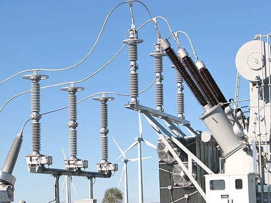
To explain in very simple words, I would say that substation is a bunch of electrical devices gathered and connected in one place. On top are clever electrical devices who control and protect others in order to everything work properly. And all devices in substation are happy, at least until something goes wrong…
 The basic things about substations you MUST know in the middle of the night!
In a less simple way, substation is the key part of electrical generation, transmission, and distribution systems. Substation transforms voltage from high to low or from low to high as necessary. Substation also dispatches electric power from generating stations to the consumption center.
Electric power may flow through several substations between the generating plant and the consumer, and the voltage may be changed in several steps.
Contents:
1. Substation classification
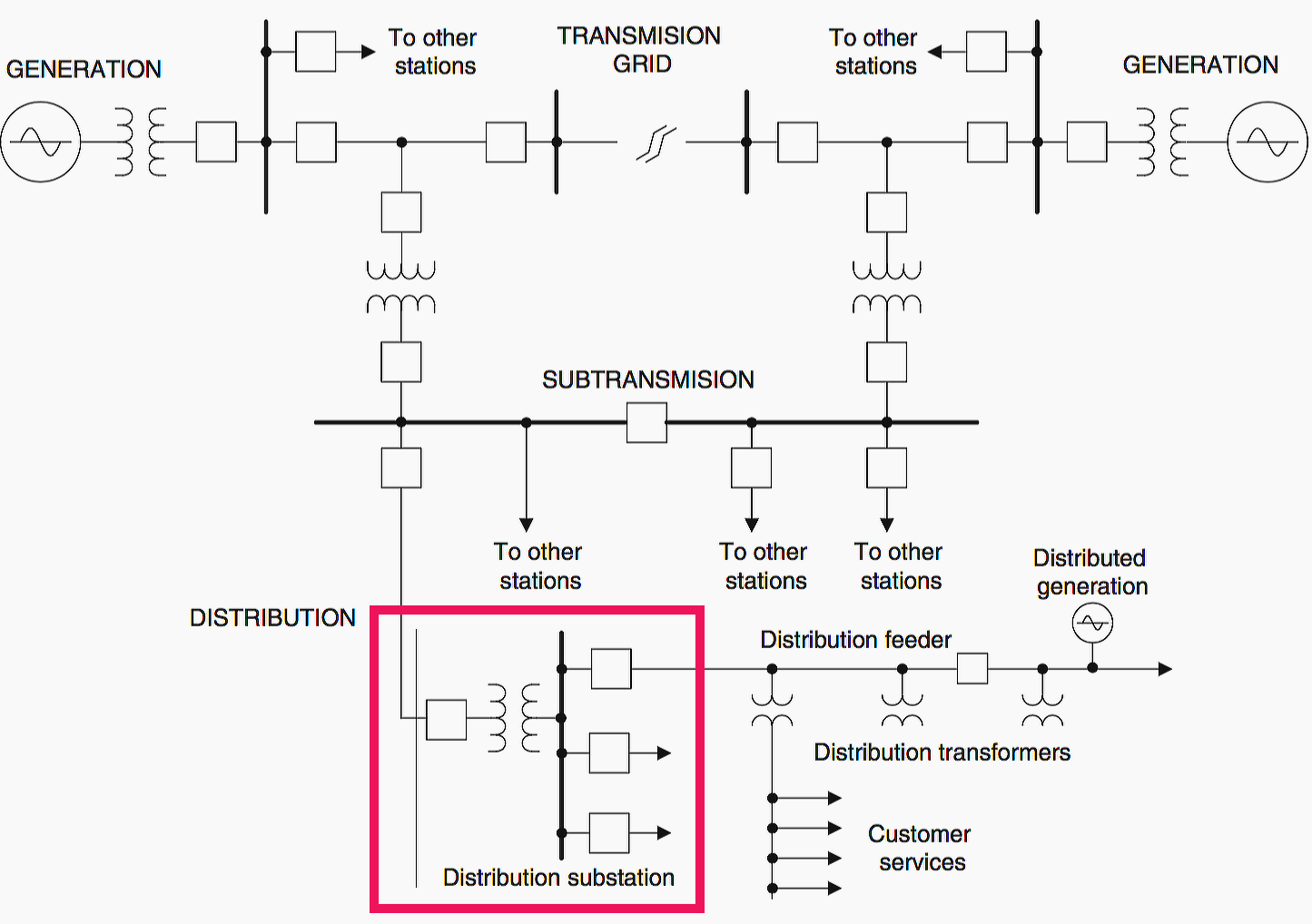
Substations can be generally divided into three major types (according to voltage levels):
1.1 Transmission substations
Transmission substations integrate transmission lines into a network with multiple parallel interconnections, so that power can flow freely over long distances from any generator to any consumer.
This transmission grid is often called the bulk power system. Typically, transmission lines operate at voltages above 138 kV. Transmission substations often include transformation from one transmission voltage level to another.
The primary function of transmission is to transmit bulk power from sources of desirable generation to bulk power delivery points.
Benefits have traditionally included lower electrical energy costs, access to renewable energy such as wind and hydro, locating power plants away from large population centers, and access to alternative generation sources when primary sources are not available.
1.2 Sub-transmission substations
Sub-transmission substations typically operate at 33 kV through 138 kV voltage levels. This kind of substations transform the high voltages used for efficient long distance transmission through the grid to the sub-transmission voltage levels
These supply lines are radial feeders, each connecting the substation to a small number of distribution substations.
Dual-source sub-transmission configuration is more reliable: Faults on one of the radial sub-transmission circuits should not cause interruptions to substations. Double-circuit faults can cause multiple station interruptions.
Single-source, radial subtransmission configuration is less reliable: Faults on the radial sub-transmission circuit can cause interruptions to multiple substations.
Also, new sub-transmission lines tend to be put underground, as development of solid-insulation cables has made costs more reasonable.
1.3 Distribution substations
Distribution substations typically operate at 11KV/0.4KV voltage levels and deliver electric energy directly to industrial and residential consumers. Note that distribution voltage level may vary in countries worldwide.
At the consumers’ premises, distribution transformers transform the distribution voltage to the service level voltage directly used in households and industrial plants. It’s usually 230 V or 400 V.
2. Substation equipment
The substation may include the following equipment:
- Power transformer or distribution transformer (depending on substation type)
- Circuit breakers
- Disconnecting switches
- Isolators
- Busbars
- Current transformers
- Potential transformers
- Lightening arrestor
- Protective relays
- Station batteries
- Earthing system
A typical substation connection diagram is shown in Figure 4.
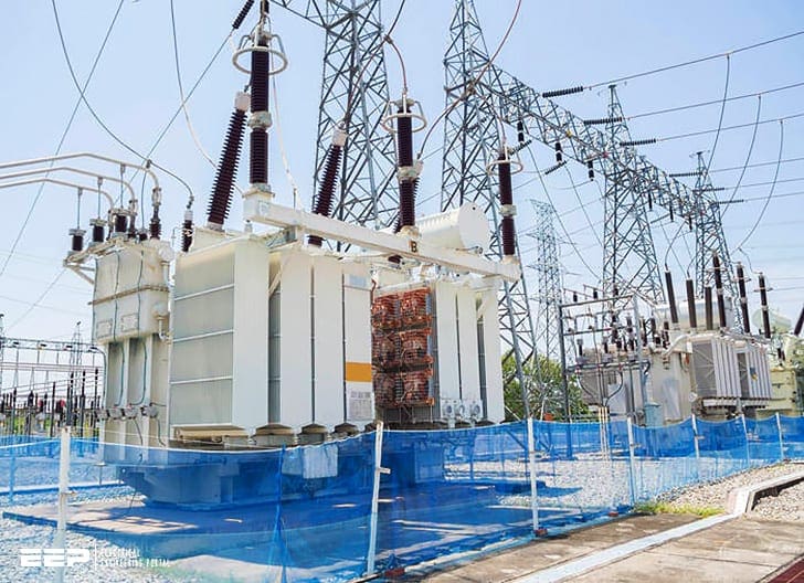
2.1 Transformers
Transformers are an essential part of any electrical power system. They come in various sizes and voltage ratings.
AC transformers are one of the keys to allowing widespread distribution of electric power as we see it today. Transformers efficiently convert electricity to higher voltage for long distance transmission and back down to low voltages suitable for customer usage.
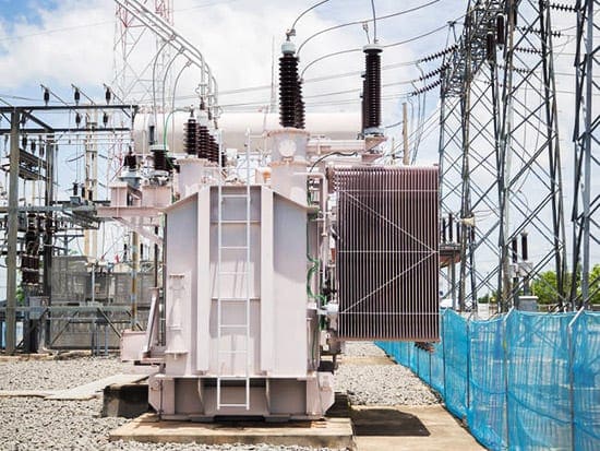
The distribution power transformers perform the necessary voltage transition from transmission (or sub-transmission) voltage level to a level suitable for power distribution. One example of such transition would be a change from 66 kV to 11 kV.
Three-phase banks, constructed from single-phase units, can also be implemented due to specific reasons like the road transportation restrictions or request for single-phase spare unit.
The power transformer is generally the most expensive single component in a primary distribution substation. In the following, the distribution power transformer features, construction and protection and their influence to the complete distribution system performance are discussed.
The focus is in mineral oil-insulated (oil-immersed) three-phase units, which form the majority of distribution power transformers in applications under IEC influence.
2.2 Circuit Breakers
Circuit breakers which control high voltages and protect other substation equipment are also located at power substations. Many outdoor substations use oil-filled circuit breakers. This type of circuit breaker has contacts immersed in an insulating oil contained in a metal enclosure.
Another type of high-voltage circuit breaks is the magnetic air breaker in which the contacts separate in the air when the power line is overloaded.
Magnetic blowout coils are used to develop a magnetic field which causes the arc produced when the contacts break. So, arc concentrated into are chutes where it is extinguished.
It should be pointed out that large arcs are present whenever a high-voltage circuit is interrupted. This problem is not encountered to any great extent in low-voltage protective equipment.
Two main circuit breaker types based on a construction are live tank breakers and the dead tank breakers. With live tank breakers, the outer surface of the breaking chamber is not earthed and is under primary voltage influence, thus “live”.
With dead tank breakers, the outer surface of the breaking chamber is earthed, thus “dead”. Dead tank breakers are generally only available for outdoor installations from 33 kV upwards.
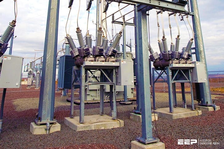
2.3 Disconnecting Switches
Disconnecting switches are used to disconnect electrical equipment from the power lines which supply the equipment. Ordinarily, disconnect switches are not operated when current is flowing through them. A high-voltage arcing problem would occur if disconnect switches were opened while current was flowing through them.
They are opened mainly to isolate equipment from power lines for safety purposes.
Most disconnect switches are the “air-break” type which is similar in construction to knife switches. These switches are available for indoor or outdoor use in both manual and motor-operated designs.
In the switchyard, the output disconnector’s poles are set up so that they are all in line. All three poles of the output disconnector will have a motor-spring-loaded drive. There is a motor-spring-loaded drive for the main links that move.
The output disconnector’s grounding switch is controlled by a similar type of mechanism. According to IEC 62271-102, the disconnector is generally class M2, which means that it needs to be able to handle 10,000 operations.
2.4 Substation Bus
The electrical and physical connection of substation buses are typically governed by safety, reliability, economy, maintainability and ease of operations. Bus is actually the electrical structure to which all power lines and transformers are connected. Generally, there are two types: open air and enclosed. Enclosed buses are used in buildings or outdoors where space is at precious.
Bus structures must be designed to withstand high short-circuit currents and large mechanical forces as a consequence.
The erroneous operation of a bus relay substantially alters system topology and greatly impacts power delivery in a distribution bus and system stability in a transmission-level bus.
2.5 Surge Arresters
The electrical installations are exposed to overvoltage stresses caused by various sources. By nature, the overvoltages caused by the sources have different characteristics in terms of magnitude, frequency, duration and rate of rise.
The overvoltage phenomena are traditionally classified in three separate categories:
- Temporary overvoltages
- Switching overvoltages
- Lightning overvoltages
In primary distribution substations, the main protective device for the installed equipment against overvoltages is the zinc oxide cap-less surge arresters. The selection of suitable surge arrester depends on several factors.
Manufacturers of surge arresters have published guidelines and selection examples to demonstrate and support the selection process.
A single- or two-phase earth fault leads to a temporary overvoltage situation in the healthy phase(s) and also in the neutral of Y-connected power transformers. The amplitude is determined by the system-earthing conditions and the duration is determined by the protection settings (fault clearance time).
The arresters have to be able to withstand the thermal stresses during these situations.
2.6 Insulators and Conductors
All power transmission lines must be isolated to avoid safety hazards. Large strings of insulators are used at substations and at other points along the power distribution system to isolate the current carrying conductors from their steel supports or any other ground mounted equipment.
Insulators may be made of porcelain, rubber or a thermoplastic material.
Porcelain insulators are widely employed for transmission and distribution applications.
The climatic conditions in coastal regions also affect material choices. In coastal regions, salt deposits on the insulator surface lead to higher leakage current on the insulator. A comparable scenario occurs when numerous dispersed chemical particles are present in the environment. All these issues are considered during the design of the transmission tower and the selection of the conductor.
2.7 Protective relays
Protective relays provide an accurate and sensitive method of protecting electrical distribution equipment from short circuits and other abnormal conditions.
Overcurrent relays are used to cause the rapid opening of electrical power lines when the current exceeds a predetermined value. The response time of the relays is very important in protecting the equipment from damage.
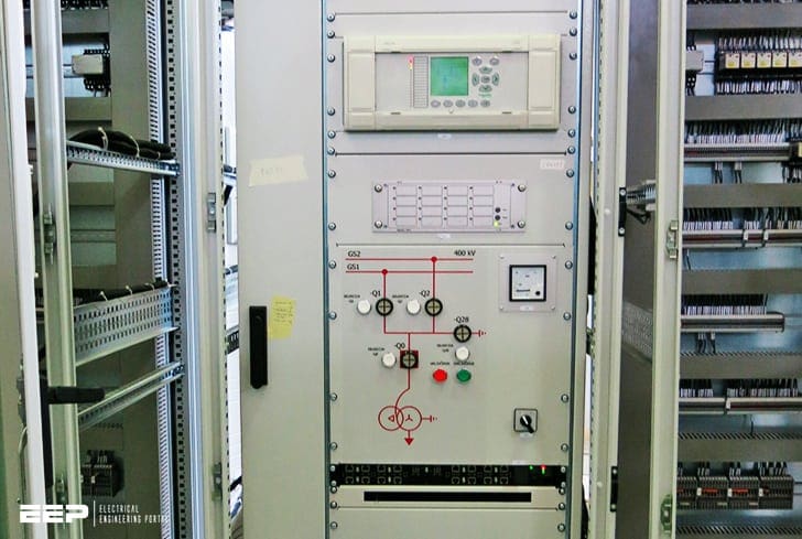
The protection relays are externally powered advanced Intelligent Electronic Devices (IEDs), also referred to as Feeder Terminals.
In a modern primary switchgear, the bay-dedicated functions like protection, control and measurement are carried out with feeder terminals. The Feeder terminal performs the assigned protection functions, carries out the local and remote control of switching devices, gathers and processes and displays measured data and indicates the status of the switching devices.
The Objectives of Relay Protection
Determining the protection relays for a power system and their settings typically throws two competing goals against one another. On the one hand, you want the system to be fully operational at all times. To this aim, all power outages, whether due to maintenance or failure, must be avoided. You would want the protective device ratings and relay settings to be as high as possible, and these values would be further desensitized by a significant time delay, giving the circuit extra time before it is tripped.
On the other side, there is concern over the safety of the load and system components.
You can see that if you err on the side of protection, you may have multiple outages to deal with, and if you lean toward system availability, you may raise equipment damage to unacceptable levels.
Further Study – Course to Relay Circuitry and Understanding Control and Protection Schematics
Course to Relay Circuitry and Understanding Control and Protection Schematics
2.8 Fuses
Since electrical power lines are frequently short-circuited, various protective equipment is used to prevent damage to both the power lines / equipment and personnel. This protective equipment must be designed to handle high voltages and currents.
Either fuses or circuit breakers may be used to protect high-voltage power lines.
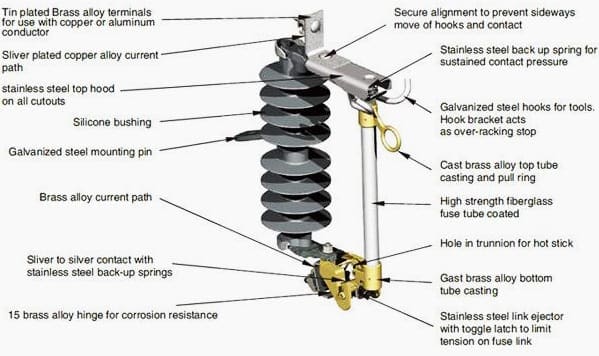
High-voltage fuses (those used for over 600 volts) are made in several ways. An expulsion-type fuse has an element which will melt and vaporize when it is overloaded, causing the power line connected in series with it to open.
Liquid fuses have a liquid-filled metal enclosure, which contains the fuse element. The liquid acts as an suppressing medium. When the fuse element melts due to an excessive current in a power line, the element is immersed m the liquid to extinguish the arc.
This type of fuse reduces the problem of high-voltage arcing.
The fuse and switch enclosure is usually mounted near the overhead power lines at a substation.
3. Substation Location
Distribution substations should be located as close to the load to be served as possible. In addition, future load requirement should be planned accurate.
The level of distribution voltage is also very important consideration. Generally, the higher the distribution voltage, the farther apart substations may be located. However, they become larger in capacity and in number of customers served as distance apart increases.
The decision of substation location must be based upon system reliability and economic factors. Among these factors are:
- The availability of land,
- Estimated operating costs,
- Taxes,
- Local zoning laws,
- Environmental factors and
- Potential public opinion.
Also considered is the fact that conductor size increases as the size of the load supplied increases. The primary voltage level affects not only the size of conductors, but also the size of regulation equipment, insulation and other equipment ratings.
Sources:
- Class notes on electrical power transmission and distribution (Department of Electrical Engineering Veer Surendra Sai University of Technology, Burla)
- Distribution Automation Handbook by ABB
- Electric Power Distribution Equipment and Systems by T.A. Short; EPRI Solutions, Inc. Schenectady, NY
Related electrical guides & articles


Edvard Csanyi
Hi, I'm an electrical engineer, programmer and founder of EEP - Electrical Engineering Portal. I worked twelve years at Schneider Electric in the position of technical support for low- and medium-voltage projects and the design of busbar trunking systems.I'm highly specialized in the design of LV/MV switchgear and low-voltage, high-power busbar trunking (<6300A) in substations, commercial buildings and industry facilities. I'm also a professional in AutoCAD programming.
Profile: Edvard Csanyi

Thank you for providing such valuable information. I am curious about the design and calculation process for lightning arrestor systems in substations. Could you please elaborate on the methods or criteria used in this context?
I started feeling queasy watching that linesman change out an insulator… I don’t know how they can do that, i would have a death grip on the pole and be screaming my head off in terror.
Very well articulated. But why in the Middle of the Night?
It’s a common expression for some important information often said by professors to students :)
Dear EEP,
I found the basic about Substation very important since in every concrete stand there must be a strong foundation, am here requesting if possible a pdf of it into my email address.
thanks
your truly follower
Excellent article, I’m interested in locating and investing in a substation, preferably in Texas.
This is a brilliant approach to the basics of substations,simple and straight forward.Keep on providing this good food for us ,potential engineers .Thank you.
So simply and can be understood very well.
Merci pour votre assistance dans le domaine électrotechnique qui ns permet d’approfondir nos connaissances
excellent presentation of substations
Nice article, but one important thing I see missing is voltage regulators for individual distribution circuits..
Very awesome presentation.
Thanks Edvaed
Very enlightening and helpful article and at the same time good reference in the field.
Excellent article . Lookingforward to more of this .
This is an outstanding write up. I like it so much. How can I get more materials on this ?
Thanks for the good job
vcb function required in video