
Estimated Study Time: 25 minutes
Substation building services
This technical article introduces five main principles involved with substation control building and switchyard services that make a lot of trouble to substation crew if poorly designed. The article covers basic internal and external lighting design, heating, ventilation and air-conditioning (HVAC) as well as fire detection and suppression practice.
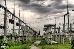
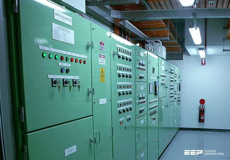 5 substation building services that usually lack of proper design and make troubles later (photo credit: ryanwilks.com.au)
Any of mentioned substation services could trigger disastrous effects like human casualties and million-dollar equipment damage. The real question is why services like these lack of proper design.
I suppose that a tight time-frame for the substation construction is responsible, as well as the lack of professionals and experts in the design and/or construction. Sometimes the lack of funds is the reason for such situations. But all in all, that’s not good.
- Substation lighting
- Substation earthing arrangements
- Heating, ventilation and air-conditioning
- Fire detection and suppression
- Cables, control panels and power supplies
- Attachment (PDF) 🔗 Download ‘Practical guidelines to electrical installation design of residential buildings’
1. Substation Lighting
Lighting schemes may be necessary for the following substation areas:
- Indoor and outdoor schemes for control buildings and indoor switchrooms under both normal and emergency (loss of alternative current (AC) supply) conditions.
- Floodlighting and emergency schemes for outdoor switchyards and door or gate access.
- Security/access road lighting together with any supplementary lighting for video camera surveillance.
- Enclosed transformer pen lighting.
The type of light source chosen for an unmanned substation control building or switchyard will be less influenced by aesthetic than technical characteristics such as colour rendering, glare, efficacy, life and cost. Without getting into details of luminaire types, let’s just mention that nowadays, LED lights are the the most common type.
Typical substation lighting levels are shown below.
Table 1 – Typical substation lighting levels
| Substation area | Standard illuminance [lux] | Limiting glare index |
| Indoor switchroom | 200 | — |
| Control rooms | 400 | 25 |
| Telecommunication rooms | 300 | 25 |
| Battery rooms | 100 | — |
| Cable tunnels and basements | 50 | — |
| Offices | 500 | 19 |
| Entrance halls, lobbies, etc. | 200 | 19 |
| Corridors, passageways, stairs | 100 | 22 |
| Messrooms | 200 | 22 |
| Lavatories and storerooms | 100 | — |
| Outdoor switchyard (floodlighting) | 20 | — |
| Perimeter lighting | 10 | — |
| Exterior lighting (control buildings, etc.) | 15 | — |
Note that flameproof lighting fittings may be necessary in the battery room because of fumes given off from unsealed batteries.
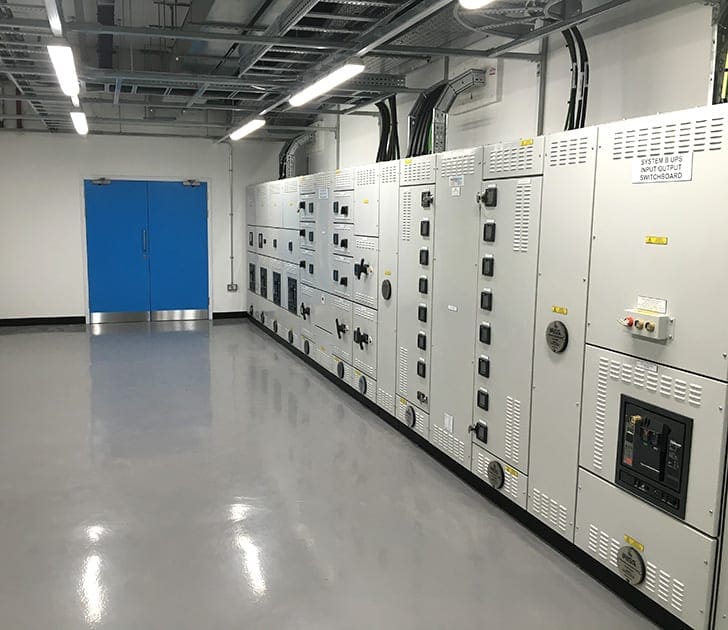
See Figure 1 – an example of lighting design of the UPS room:
2. Substation earthing arrangements
The characterization of LV building services AC distribution systems may be described by the type of earthing arrangements used. Effective earthing is essential:
Reason #1 – To prevent the outer casing of the apparatus and conductors rising to a potential which is dangerously different from that of the surroundings. Where there is an explosive risk there may be a danger from very small voltage differences causing sparking.
Reason #2 – To allow sufficient current to pass safely in order to operate the protective devices without danger.
Reason #3 – To suppress dangerous earth potential gradients.
Earthing methods are defined by a three letter coding:
First letter – defines the state of the supply system in relation to earth:
- T = Directly earthed system at one point.
- I = Either all live parts are insulated from earth or one point connected to earth through an impedance.
Second letter – defines the state of the exposed conductive parts of the installation in relation to earth.
- T = Exposed conductive parts connected directly to earth, independent of any earthing of a point on the supply system.
- N = Exposed conductive parts connected directly to the earthed point of the supply system, normally the supply transformer neutral point.
Third letter – defines the earthing arrangement of the system conductors.
- C = Combined neutral and earth conductors.
- S = Separate neutral and earth conductors.
Five common arrangements are shown in Figure 2. The TN-S system, using separate neutral and protective conductors throughout the network, is the recommended method for installations in hazardous areas such as substations feeding chemical plants.
The neutral and protective conductors may also be combined into a single conductor on part of the system (TN-C/S) or combined into a single conductor throughout (TN-C).
In the TT system, with exposed metal bonded directly to earth, quick acting sensitive earth leakage protection is required.
Irrespective of what earthing system is used it will not be effective unless it is frequently checked to ensure that all earth bonds are mechanically strong and free from corrosion. Furthermore, earth impedance should be monitored and recorded so that any change can be detected and the appropriate action taken.
Learn substation earthing best practices in details here.
3. Heating, Ventilation and Air-Conditioning
3.1 Air circulation
The correct air circulation or number of air changes per hour is essential to ensure comfort of substation operations and maintenance personnel. The number of air changes depends on the number of personnel and size of the room but a minimum of four fresh air changes per hour is recommended.
In addition, it is necessary to prevent the build up of dangerous gases such as may occur in a battery room using vented cells. Typical air changes per hour for different substation building areas are listed below:
Table 2 – Typical air changes per hour for different substation building areas
| Substation area | Air changes per hour |
| MV and/or HV switchrooms | 4 to 8 (30 to 60 for smoke removal) |
| LV AC and/or DC switchrooms | 4 to 8 |
| Control and relay rooms | 4 to 8 |
| Battery rooms | 6 to 10 |
| Control and communication rooms | Control and communication rooms 4 to 8 (overpressures via a filter may be specified to prevent ingress of dust into sensitive equipment partly depending upon the equipment enclosure protection (IP) rating and need for adequate heat dissipation) |
| Offices | 4 to 8 |
| Toilet and wash rooms | 10 to 12 |
| Mess room | 10 to 12 |
| Corridors | 3 to 6 |
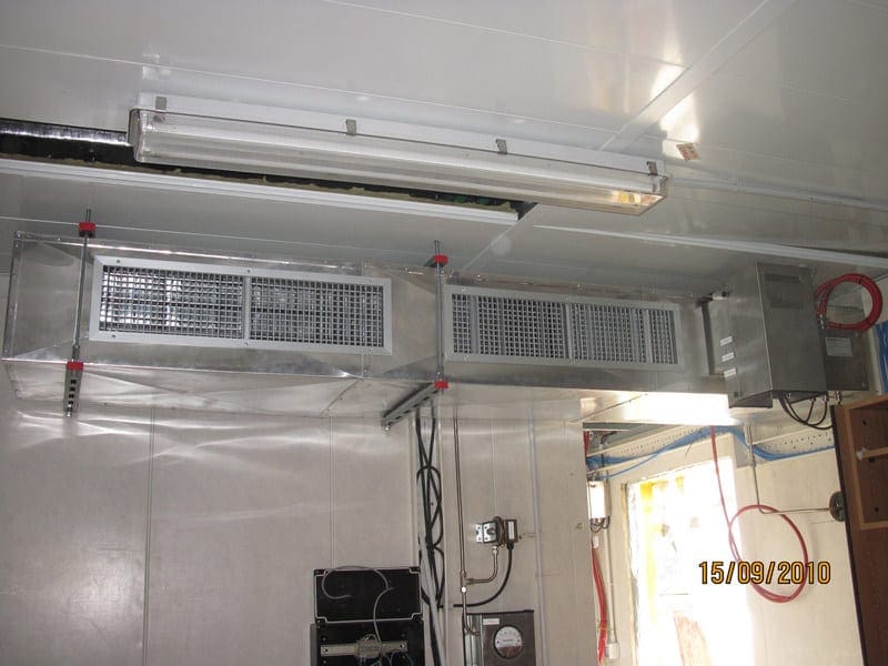
All ductwork must be designed in conjunction with the fire safety engineers in order to ensure that the fire zoning is reflected in the ductwork.
This is especially important where migration of smoke from one zone to another could be a substantial hazard (See Figure 3). The need for zonal control also applies to cable trenches running through different fire zones within the substation building.
3.2 Air-conditioning
The internationally recognized standard used for the design of Heating, Ventilation and Air-Conditioning (HVAC) is that produced by:
- In US by ASHRAE (American Society of Heating, Refrigeration and Air-Conditioning Engineers)
- In UK by CIBSE (Chartered Institute of Building Services Engineers)
Since this is a very specific subject, only a brief introduction is given here. Areas of substation buildings should be air-conditioned in the following ways:
Related electrical guides & articles


Edvard Csanyi
Hi, I'm an electrical engineer, programmer and founder of EEP - Electrical Engineering Portal. I worked twelve years at Schneider Electric in the position of technical support for low- and medium-voltage projects and the design of busbar trunking systems.I'm highly specialized in the design of LV/MV switchgear and low-voltage, high-power busbar trunking (<6300A) in substations, commercial buildings and industry facilities. I'm also a professional in AutoCAD programming.
Profile: Edvard Csanyi
