
Estimated Study Time: 31 minutes
Substation bus and switchgear
The substation bus and switchgear are the parts of the power system used to direct the flow of power to various feeders and to isolate apparatus and circuits from the power system. These parts include the busbars, circuit breakers, fuses, disconnection devices, current transformers (CTs), voltage transformers (VTs), and the structure on or in which they are mounted.
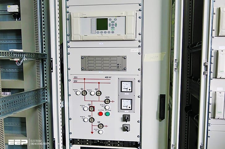 The essentials of LV/MV/HV substation bus overcurrent and differential protection (on photo: HV protection panel; credit: EEP)
The term bus refers to the bus within an assembly of equipment: medium-voltage, metal-enclosed switchgear, medium-voltage control, low-voltage switchgear, power switchboards, panelboards, motor control centers (MCCs), bus duct.
- Bus protection in general
- Types of buses and arrangements
- Bus overcurrent protection
- MV and HV bus differential protection
- Backup protection
- LV bus conductor and switchgear protection
- Conclusion
1. Bus protection in general
To isolate bus faults, all power source circuits connected to the bus are opened electrically by circuit breakers responding to relay action, by direct-acting trip devices on low-voltage circuit breakers, or by fuses. This disconnection shuts down all loads and associated processes supplied by the bus and may affect other parts of the power system.
In view of the system downtime resulting from a bus fault, the equipment should be designed to be as nearly fault proof as practicable. For example, the use of metal-clad switchgear enhances reliability because the enclosure protects the bus from direct lightning strokes.
Medium-voltage metal-clad switchgear uses insulated busbars as standard. Such busbars reduce accidental faults caused by foreign objects or rodents. Using metal-enclosed bus duct or insulated cable not directly exposed to lightning contributes to reliability.
To further reduce the occurrence of faults, the bus and associated equipment should be installed in a location where they are least subjected to deteriorating environmental conditions.
A preventive maintenance program is essential to detect deterioration, to make repairs, and to check and test relay performance before a fault occurs.
Each equipment assembly should be provided with a main protective device for each power source, either as an integral part of the assembly or in a remote location. If the main protective device is omitted in an assembly and provided by an upstream device, the installation may be acceptable if coordinated protection is provided.
The main circuit breaker sometimes is omitted at the secondary of a power transformer that is protected on the primary.
This setup reduces the effectiveness of secondary bus protection because the transformer reduces the sensitivity of the primary protection for secondary faults.
When industrial power systems are grounded through a resistance or reactance to limit fault damage, the short-circuit current available to detect a ground fault is small and requires sensitive protective relaying.
When supplementary bus differential protective relaying is used, it is essential that it operate only for bus or switchgear faults. False tripping on external faults is unacceptable.
2. Types of buses and arrangements
The substation bus may have many different arrangements depending on the requirements for continuity of service requirements for the bus and essential feeders supplied from the bus. Refer to IEEE Std C37.
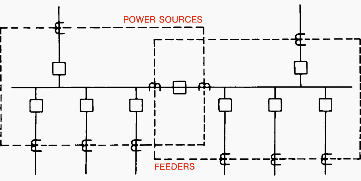
The methods of protecting substation buses and switchgear vary depending on voltage and the arrangement of the buses. The bus arrangements most applicable to industrial power systems are shown in Figure 1, Figure 2, Figure 3, and Figure 4 below
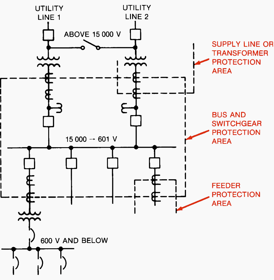
A simple radial system is similar to Figure 1 except with only one utility line and supply transformer. Industrial power system voltages fall into three categories: above 15 000 V, from 15 000 V to 601 V, and at or below 600 V.
Usually the industrial facility provides the high-voltage bus relaying. Compliance with utility practice is mandatory in most cases.
3. Bus overcurrent protection
Most systems are radial, and overcurrent protection on each incoming power source circuit can provide adequate bus protection. On MV and HV systems, fuses or overcurrent relays that trip circuit breakers are used. They are supplemented with sensitive ground relays when the system is lowresistance-grounded.
On LV systems, most applications use circuit breakers or fuses. The introduction of electronic trip units for low-voltage circuit breakers to perform the sensing and timing functions provided significant improvements in the quality of protection for low-voltage circuits and apparatus.
Separate circuitry detects ground faults at much lower levels and clears them much faster than is possible with direct-acting electromechanical phase-overcurrent devices alone.
Electronic trip units are normally available with integral sensitive ground elements.
The NEC code requires ground-fault protection on solidly grounded wye-connected electric services of more than 150 V to ground, but not exceeding 600 V phase to phase, for the following devices:
- Any service-disconnecting means rated 1000 A or more (see Article 230-95)
- Any feeder disconnect rated 1000 A or more (see Article 215-10)
- Each building or structure main disconnecting means rated 1000 A or more (see Article 240-13)
Overcurrent relays and trip devices should have time-delay and high-current settings to prevent opening the source circuit breakers upon the occurrence of a feeder fault. As a result, they cannot provide sensitive high-speed bus and switchgear protection.
An inverse or definite time-overcurrent relay connected to a CT in the power transformer neutral-to-ground circuit provides good sensitivity for ground faults. It should be set to be selective for feeder faults.
If the feeders have ground-sensor instantaneous protection, only a short-time delay is needed on the relay in the transformer grounding circuit.
Because most faults are ground faults or eventually become ground faults, good ground-fault protection greatly improves bus overcurrent protection.
4. MV and HV bus differential protection
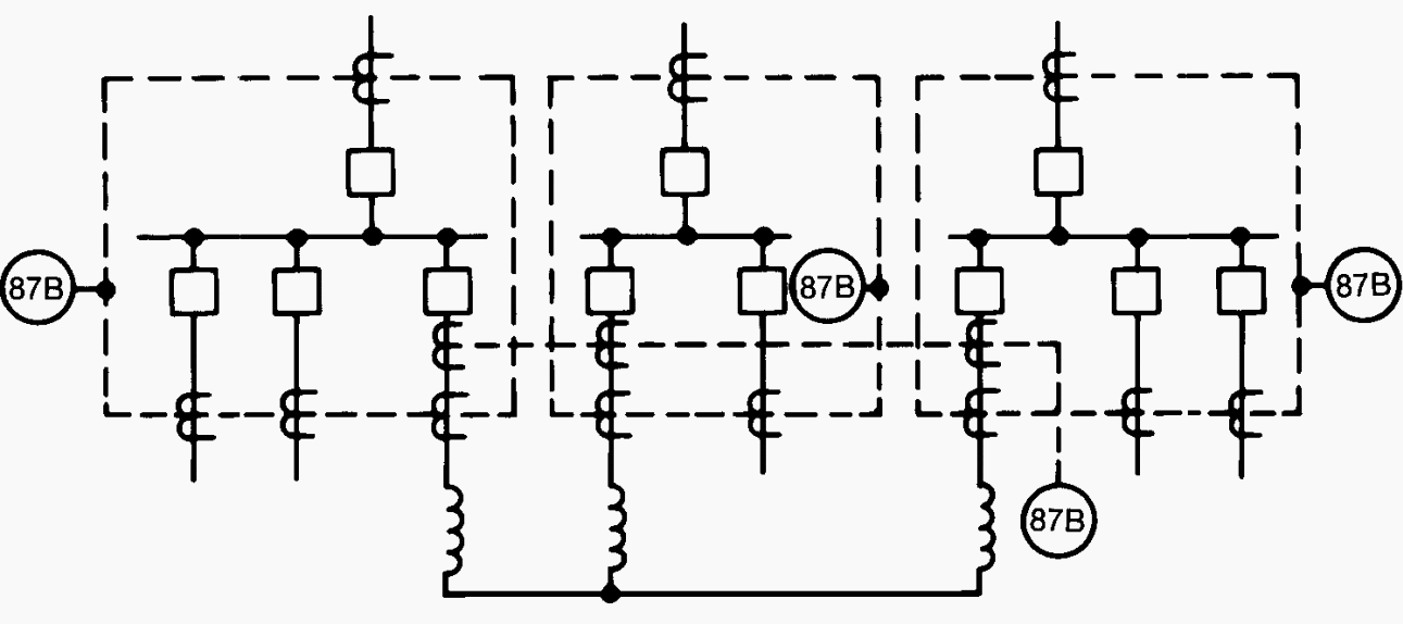
Bus differential relaying can provide high-speed, sensitive, improved protection and selectivity for buses and switchgear. It is sometimes used in addition to overcurrent protection and permits complete overlapping with the other power system relaying as indicated in Figure 1, Figure 2, Figure 3, and Figure 4 above.
Bus differential relaying normally is applied to more complex systems, which have multiple sources and perhaps multiple buses at the same voltage level. The principle reason for selecting such protection is to ensure protective device coordination that de-energizes the bus only when absolutely necessary.
This goal justifies the extra cost of high-speed bus differential relaying.
This addition provides relatively inexpensive selective protection using standard transformers and an auxiliary CT connection.
Differential relaying is provided to supplement overcurrent protection. It is frequently used on a 15 kV bus, sometimes on a 5 kV bus, and rarely on any low-voltage bus.
The following factors determine whether this relaying should be provided:
Factor #1 – Degree of exposure to faults.
For example, open outdoor buses have a high degree of exposure, and metal-clad switchgear, properly installed and in a clean environment, have minimum exposure. Contaminated environments increase the possibilities of faults, and equipment located in these environments needs better protection.
Factor #2 – Power system stability
The capability of a system to return to a stable, steady-state mode of operation after a system disturbance may require high-speed bus differential relaying.
Factor #3 – Use of sectionalized bus arrangements
Sectionalized bus arrangements make differential protection more useful and desirable, particularly when secondary-selective distribution systems are used. The faulted bus can be isolated quickly and continuity of service maintained to a portion of the load served by any other bus.
Factor #4 – Effects of bus failure on other parts
Effects of bus failure on other parts of the power system and associated processes. If a long scheduled outage period for repairs can be tolerated, differential protection may not be economically justified.
On a major plant bus, the cost of differential relaying is usually insignificant when compared with the reduction in damage to the equipment and the reduced scheduled outage of important plant or process facilities.
On a bus fed by a local generator, bus differential relaying is recommended to clear the bus quickly and hold the rest of the system together. The overcurrent relays used to protect generator circuits generally take considerable time to operate.
The differential protection methods generally used (in the order of the quality of protection they provide) are:
- Voltage-responsive and linear coupler
- Percentage differential (where applicable)
- Current responsive
- Partial differential (sometimes not considered a differential scheme and called current summation)
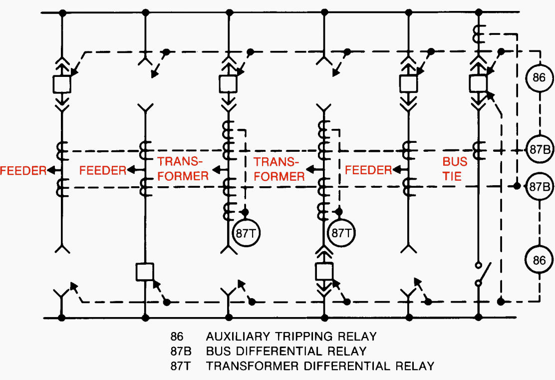
Because the differential relay should trip all circuit breakers connected to the bus, a multicontact auxiliary relay is needed. This auxiliary device should be a high-speed lockout relay, with contacts in the circuit breaker closing circuits to prevent panic manual closing of a circuit breaker on the fault. The lockout relay should be reset by hand before any circuit breakers can be closed.
4.1 Voltage differential relaying scheme
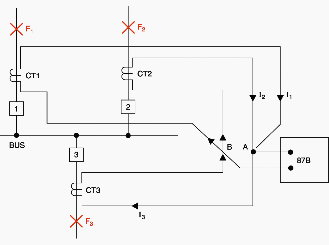
Voltage differential relaying uses “through” iron-core CTs. Using a voltage-responsive (or high-impedance) operating coil in the relay overcomes the problem of CT saturation. Separate CTs are required in each bus-connected circuit as shown in Figure 7.
Voltage differential bus protection is not limited as to the number of source and load feeders and has the following features:
- High-speed operation on the order of 1 cycle to 3 cycles.
- High sensitivity that can be set to operate on low values of phase- or ground-fault currents in most installations.
- Relay that operates from all standard bushing CTs and from switchgear through CTs with distributed windings.
- Relay that is not adversely affected by CT saturation, dc component of fault current, or circuit time constant.
- Discrimination between external and internal faults, obtained by relay settings with no required restraint or time delay.
All CTs should have the same ratio unless high-impedance relays suitable for use with different ratio CTs are used. Auxiliary CTs should not be used to match ratios.
All CTs should have low secondary leakage reactance. Wound CTs are generally not suitable.
Bushing CTs constructed on toroidal cores with completely distributed windings generally have negligible leakage reactance. A distributed winding starts and ends at the same point on the core.
Through CTs having suitable characteristics are available for use in switchgear assemblies.
The relay should fulfill two requirements:
- First, it should not trip for any fault external to the zone of protection.
- Second, it should be capable of operating for all faults internal to the zone of protection.
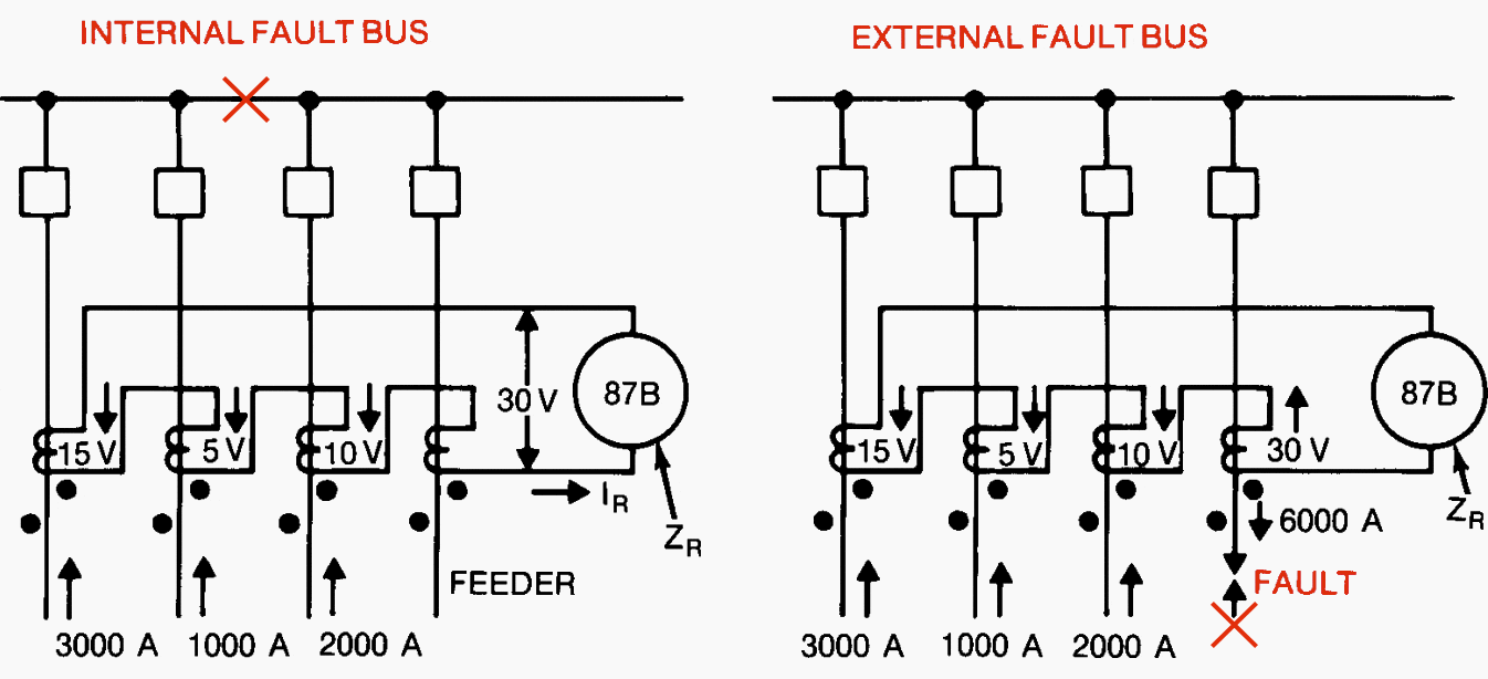
Considering the first requirement, refer to Figure 7 above. Assume a three-circuit-breaker bus with a fault at the location shown. Consider for simplicity only one of the three phases.
For the fault F3 indicated, the fault current I3 flows through Circuit Breaker 3 with the currents flowing through Circuit Breaker 1 and Circuit Breaker 2. Each current is smaller than, but together sum up to, I3.
Assume that the CTs behave ideally. Then the CT secondary current produced at Circuit Breaker 3 balances the sum of the currents produced at Circuit Breaker 1 and Circuit Breaker 2. This current circulates in the CT secondary circuits and produce little, if any, voltage across Point A and Point B.
If, for some reason, the CT secondary current at Circuit Breaker 3 does not balance the sum of the currents produced by the CTs at Circuit Breaker 1 and Circuit Breaker 2, excess or difference current is forced to flow through CT 3 and cause the voltage across Point A and Point B to increase to a point where the relay (Device 87B) will tend to operate.
It thus becomes apparent that the CT at Circuit Breaker 3 has a greater tendency to saturate than the CTs at Circuit Breaker 1 and Circuit Breaker 2, for the given fault location, because Circuit Breaker 3 sees the total current while the other two circut breakers each see only a fraction of the total.
For complete saturation, the mutual reactance of the bushing CT approaches zero. If it has no appreciable secondary leakage reactance, then the only secondary impedance of the CT is its winding resistance.
Thus, for complete saturation of the CT at Circuit Breaker 3, the voltage developed between Point A and Point B is the product of (I1 + I2) and the sum of the total resistance in the circuit between Point A and Point B and CTs at Circuit Breaker 3 (including the CT secondary resistance).
The differential relay is set so that it does not operate for this voltage. It is obvious that this voltage depends on the magnitude of the fault current, the type of fault, and the total resistance. In the case of internal faults, the secondary currents do not circulate, but rather result in a high enough secondary voltage to cause the relay to operate.
When offset-fault current occurs or residual magnetism exists in the CT core, or both, an appreciable DC component in the secondary current is present. This condition has caused false tripping when simple unrestrained low-impedance relays are used for bus differential.
Voltage differential relays are made insensitive to the DC component by connecting the relay-sensitive operating coil in series with a capacitor and reactor.
The circuit is resonant at the fundamental power frequency, and the DC component is blocked by the series capacitor.
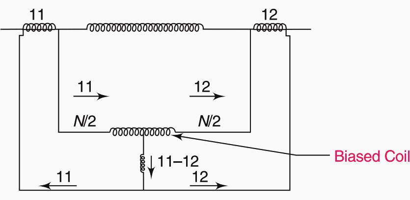
4.2 Air-core CT (or linear coupler) method
The air-core CT method provides extremely reliable high-speed bus protection. It is highly flexible to future expansion and system changes. The couplers can be open-circuited without any difficulties to simplify switching circuits.
Therefore, it is free of any DC or AC saturation.
The linear couplers of the different circuit breakers are connected in series and produce secondary voltages that are directly proportional to the primary currents going through the circuit breakers, as shown in Figure 8.
With the simple series circuit shown in Figure 8:
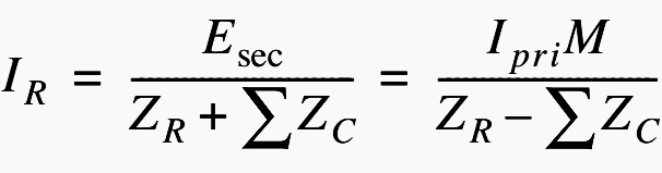
where:
- Esec is voltage induced in linear coupler secondary,
- Ipri is primary current (rms symmetrical),
- IR is current in relay and linear coupler secondary,
- M is mutual impedance, 0.005 W, 60 Hz,
- ZC is self-impedance of linear coupler secondary,
- ZR is impedance of relay.
For the conductor within the toroid, 5 V is induced per 1000 A of primary current. Therefore, by design, the mutual impedance M is 0.005 W, 60 Hz. In other words, Esec = Ipri × M.
Electronic voltage differential relays are also available, providing faster operating times than electromechanical relays.
4.3 Percentage differential relay scheme
Where relatively few circuits are connected to the bus, relays using the percentage differential principle may be employed. These relays are similar to transformer differential relays.
Variation in the characteristics of the CTs, particularly the saturation phenomena under short-circuit conditions, presents the greatest problem for this type of protection and often limits it to applications where only a limited number of feeders are present.
4.4 Current differential relaying scheme
When voltage or linear coupler differential protection cannot be economically justified, a less expensive current differential scheme may be considered. This scheme utilizes simple induction overcurrent relays connected to respond to any difference between the currents fed into the bus and the current fed from the bus.
The CT arrangements are the same as shown in Figure 1, Figure 2, Figure 3, and Figure 4. The connections are as shown in Figure 7.
4.5 Partial differential protection scheme
Partial differential protection, sometimes called summation overcurrent relaying, is a modification where one or more of the load circuits are left uncompensated in the differential system (see Figure 10). For this reason, naming it a differential scheme may be a misnomer.
This method may be used as primary protection for buses with loads protected by fuses, as backup to a complete differential protection scheme, and as local backup protection for stuck load circuit breakers, which fail to operate when they should.
The phase overcurrent relays are set above the total bus load or the total rating of all loads supplied from the bus section.
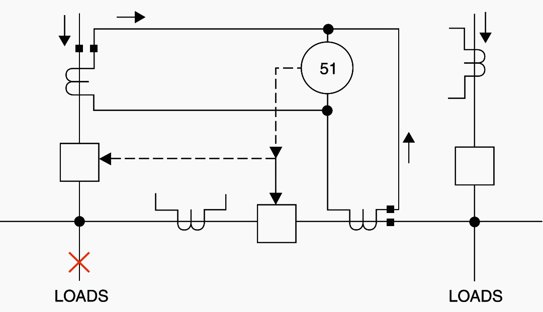
When a normally closed tie breaker separates loads as shown in Figure 10, this scheme can provide selectivity between the two sources.
In a conventional scheme with relays on each incoming line, a fault on either bus results in a loss of both incoming lines because their settings are identical. With the partial differential scheme, a fault on one bus causes a summation of currents in one set of relays, and a subtraction of currents in the other set of relays (not shown).
Partial differential relays should provide enough time delay to be selective with relays on the load circuits. Consequently, the sensitivity and speed of partial differential protection is not as good as for full differential protection.
5. Backup protection
If the primary protective system fails to operate as planned, some form of backup relaying should be provided in the industrial power system or in the power supply system.
Bus backup protection is inherently provided by the primary relaying at the remote ends of the supply lines. This setup is known as remote backup protection.
It may not be adequate because of system instability and effects on other power systems, and local backup relaying may be necessary. The performance of various remote and local backup relaying schemes has been analyzed.
However, those schemes are normally applied only on buses where the extra expense can be economically justified.
6. LV bus conductor and switchgear protection
Low-voltage bus and switchgear are often protected by current-limiting fuses, sized to the full-load rating when bus and switchgear have bus bracings that are less than the available fault current. Current-limiting fuses are often used to limit the fault current to levels that the bus and switchgear can handle.
To reduce the possibility of destructive arcing ground faults on 480Y/277 V systems, the 480 V bus may be insulated.
Preventing a ground fault from occurring is far better than shutting down a system or a part of a system after a ground fault has occurred.
7. Conclusion
Because of its location and function in the electric power system, the bus and switchgear should be designed, located, and maintained to prevent faults. The preferred practice for bus switchgear protection above 600 V is voltage-responsive or linear coupler differential relaying with the power system designed with a sectionalized bus so that continuity of service can be maintained to a portion of the load.
The best protective relaying in a single-bus arrangement operates to cut off power to all circuits supplied by the bus.
Fast clearing of faults also can save lives by minimizing explosion and fire aftermath. Furthermore, fast clearing of human-contact faults has saved lives or reduced injury.
Reference // IEEE Recommended Practice for Protection and Coordination of Industrial and Commercial Power Systems
Related electrical guides & articles


Edvard Csanyi
Hi, I'm an electrical engineer, programmer and founder of EEP - Electrical Engineering Portal. I worked twelve years at Schneider Electric in the position of technical support for low- and medium-voltage projects and the design of busbar trunking systems.I'm highly specialized in the design of LV/MV switchgear and low-voltage, high-power busbar trunking (<6300A) in substations, commercial buildings and industry facilities. I'm also a professional in AutoCAD programming.
Profile: Edvard Csanyi

Thanks so much am done electrical engineering this is really help to understand the power systems your clear and simple I need portal so that I can be learning more
Am into Electrical industrial work Please I need a training with ELECTRICAL ENGINEERING PORTAL to improve my skills in Electrical Engineering work please am really in love with EEP and I enjoy what dey are doing please I really need Electrical Engineering Portal to train me if is to pay for the training I will really pay and if is to work for Electrical Engineering Portal for 10 years without pay after the training I will do it please get back to me thanks
Hi Edavrd,
Thank you for this very interesting article, just I have a quick question abut Iron-CTs, Bushing CTs constructed on toroidal cores in differential use, is the distance entry points installing and the relay is influencing the fault measurement?
Regards
If add stop covering the content then it would be less irritating.
Thanks Edvard,
One comment relating to fig. 1:
the ‘tie’ switch between the two >15 kV transformers is shown as ‘open’ which is presumably its normal position. If an external fault occurs, (say on “Utility Line 2”), then that line may be de-energized by a remote device. The tie-switch can then closed by operator action. However he must remember to open the circuit breaker for U.L.2 first; otherwise there would be back-feed into the faulty Line 2, and the fault might still be present. Utility Line 1 would now be feeding both transformers – but it’s no doubt designed to be capable of this.
But maybe the fault has cleared and Utility Line 2 is now re-energized. The circuit breaker on U.L.2 can now be closed again but the tie-switch probably needs to be re-opened, otherwise the maximum fault current at either of the transformers would have doubled. (And of course it’s not guaranteed that the utility co. would permit two of their lines to be connected in this way.)
Regards, David.
There is ALWAYS an interlock, electrical, logical, and if possible mechanical, between these parts to guarantee no mal-operation. It is typical for any MTM system achieved with or without a communication pilot.
I am very thankful/grateful to you sir for making such a great platform(EEP) for electrical enthusiasts.