
Estimated Study Time: 37 minutes
Substation Control Systems
To ensure the substation is run efficiently, a control and monitoring systems are needed. These systems should display the current status of all plant equipment, including alarms and secondary system indicators. They should also provide digital outputs to open and close switchgear, raise and lower taps on transformers, and show analogue values for key parameters like voltage, current, megawatts, and megavars.
 Substation control and monitoring systems: The eyes and ears of every power system
Aside from the standard indicators and controls, additional functions like synchronizing, reactive and voltage control, operational and safety-related interlocking, load control to prevent frequency collapse, etc., are also possible to implement.
Nevertheless, the primary topics covered in this technical article are synchronization, interlocking operations, and the substation control system.
There are typically three tiers of supervision and control, or points of human machine interface (HMI), in a substation’s control and monitoring system. However, just the first two tiers of control may be used, as the exact number of tiers relies on regional norms.
- Bay Control: In the switchyard/switchgear buildings (bay control)
- Station Control: At the substation control room (station control)
- From a central network control center: Network control, remote control center, regional control center
Typically, the decision to switch between bay or station control is made from the bay control point, though it can also be done on an equipment-by-equipment basis. The rules for switching control points, known as control arbitration, are up to the user. The station control point is where you’ll make the decision as to whether the circuit is under network control or station control.
From one facility to the next, you should expect to see a wide range of signals, alarms, and regulated equipment.
For a visual representation of the hardware present at the HMIs, see Figure 1 below.
There is currently a marked difference between traditional human-machine interfaces and those that are computer-based, thanks to the ever-increasing usage of digital technology in substation equipment. The use of computer-based HMI is on the rise in station control rooms, in addition to its prevalence at the network control level.
On the other hand, the station level does still have a few traditional HMIs. Common and traditional HMI at bay level is direct wire control.
Ok, let’s get into the details!
- The Good Old School HMI
- Computer-Based Digital HMI
- Substation Computer Performance
- Control From the Substation
- Control From a Network Control Center
- Architectures of Control Systems
- The Need For Substation Extension and Modification
- Minimizing Undesirable Operations in the Control System
- Interlocking Systems
- Synchronizing and System Stability
- BONUS! Download Guide To Power System Protection For Relay Designers (PDF)
1. The Good Old School HMI
On the equipment itself or in nearby local control cubicles, you’ll find the good ol’ standard HMI at bay level, which consists of control switches, indicator LEDs, and meters. In most cases, these facilities are utilized when the controlled plant is being serviced or as a fallback in case the station level or network control center fails.
On the station level, the primary control room is where you should find the control panels. The human-machine interface (HMI) devices should be organized according to circuits, and the open/close switches should only operate devices in the same substation area as the panel itself.
Figure 1 – An example of human machine interface (HMI) locations
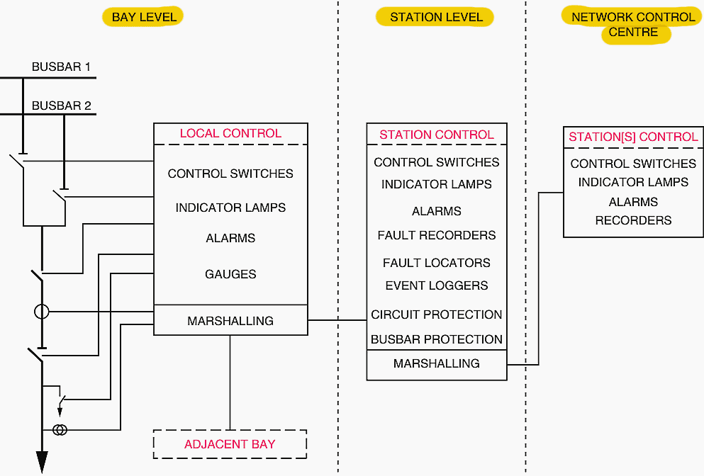
The substation layout should be depicted in a mimic diagram, which is often a single-line figure. The purpose of the mimic board is to provide operational staff with an overall perspective of the state of the switchgear. It could be assembled from separate circuit control panels that are placed side by side.
The main equipment layout should be the basis for the arrangement.
To turn off alarms that have been reset, there should be a reset button.
To start the steady-state illumination of all alarm windows, you’ll need to press a lamp test button. Separate windows, such as a red display rather than a white or amber one, should be used for trip or protection-triggered alarms. All switches, including controls and selectors, must be of the approved variety that meets all applicable standards, including IEC 60337.
To operate the control switches, you’ll need to use two separate actions or use both hands. The devices used for indication must be of the approved variety and conform to recognized standards like IEC 60051.
Figure 2 – HMI panels of an old 132 kV substation

2. Computer-Based Digital HMI
Distributed computer systems are the backbone of computer-based human-machine interfaces. At the network level, such systems were commonplace, but at the substation control level, they have only been used since the 1990s. Interfacing with machinery and relaying data to control rooms, remote terminal units (RTUs) play an essential role.
Remote control units (RTUs) will take digital and analogue data and send out control signals.
Depending on the level of redundancy needed, the following things may be utilized in different quantities by the human machine interface:
- Visual display unit (VDU)
- Alphanumeric keyboard
- Printer
- Plotter
- Trackball
- Joystick
- Special function panel
- Mouse
No less than full-graphic, multi-color visual display systems capable of continuous operation around the clock are required. Here is the data that has to be shown:
- Information that cannot be changed (such as a substation single-line schematic)
- Variable operating parameters
- Real-time dynamic variables
Each control panel has to have an operator’s keyboard with dedicated function keys so that commands can be typed in. You can enter data and run the computer and substations in general using the system keyboard. On top of that, the system might necessitate an alphanumeric keyboard.
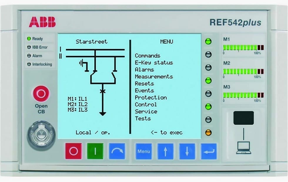
All control commands to impact the operation from an HMI typically require two stages of control: select-check-execute.
Figure 3 – LCD display of ABB’s protection relay REF 542plus HMI
3. Substation Computer Performance
To provide the required system dependability, functional availability, and ease of equipment maintenance, the kind and configuration of computer-based control equipment for substation secondary system applications should be carefully considered.
3.1 Master Station Computer
It is imperative that the HMI’s underlying computer system, the master station, has exceptional stability and practically constant functional availability. The standard method for meeting these demands is to implement hardware redundancy for the key components.
When the online unit fails, the redundant components are often set to activate automatically.
Figure 4 – Master substation computer
3.2 Subsystems Computers
Although the reliability of computer subsystems used for distributed data collecting should be top-notch, it is often acceptable to have the odd breakdown, as it will typically only impact a small portion of the entire system.
Component selection should be of a high grade to provide a long mean time between failures, however redundancy is typically not used for economic reasons.
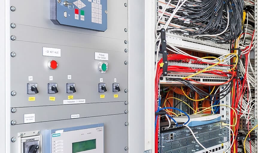
3.3 Communications
The ability to communicate is crucial for distributed computing systems. In the absence of physical routing for communication channels, stringent mechanical or electrical protection is necessary. It is recommended to offer main and standby channels over physically segregated paths in situations where the functions related to subsystems computers are critical.
In most cases, adequate availability can be achieved using just one channel.
Figure 5 – Digital protection panel: IEC 61850 communications
3.4 Computer Loading
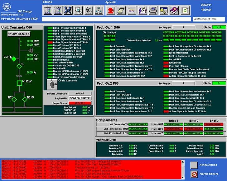
When a power network is functioning in a normal state, which it is for the majority of the time, computer-based control systems often have no trouble handling all of the activities connected with updating telemetered data and providing support for the human machine interface (HMI). Nevertheless, when there are significant disruptions to the network, the amount of data that is telemetered and the processing that is connected with the HMI will both increase in the same proportion.
While it is possible to reduce these criteria to some degree in the event of catastrophic disruptions, it is imperative that no data be lost under any circumstances.
Figure 6 – HMI screen of OHL 110 kV details page
4. Control From the Substation
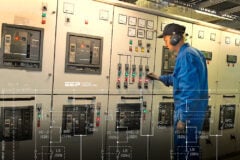
Previously, high voltage (HV) substations typically included on-site personnel who oversaw and managed the substation. The substation control room was responsible for monitoring and controlling the substation’s operations through local control.
The local control comprises a data collection system and a command issuance mechanism, known as the Human-Machine Interface (HMI). The data gathering system provides comprehensive information regarding the status and location of circuit breakers, disconnectors, and earthing switches, as well as line loads, transformer temperatures and loadings, voltage levels, relay functions, and time-stamped events.
In the event of a failure in control from the substation control room, an alternative control system for circuit breakers, disconnectors, earth switches, and other components can be activated from control cubicles situated on or near the primary equipment.
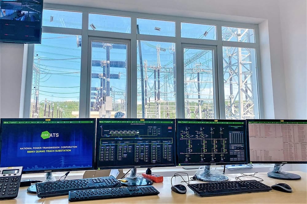
Figure 7 – Control From the Substation
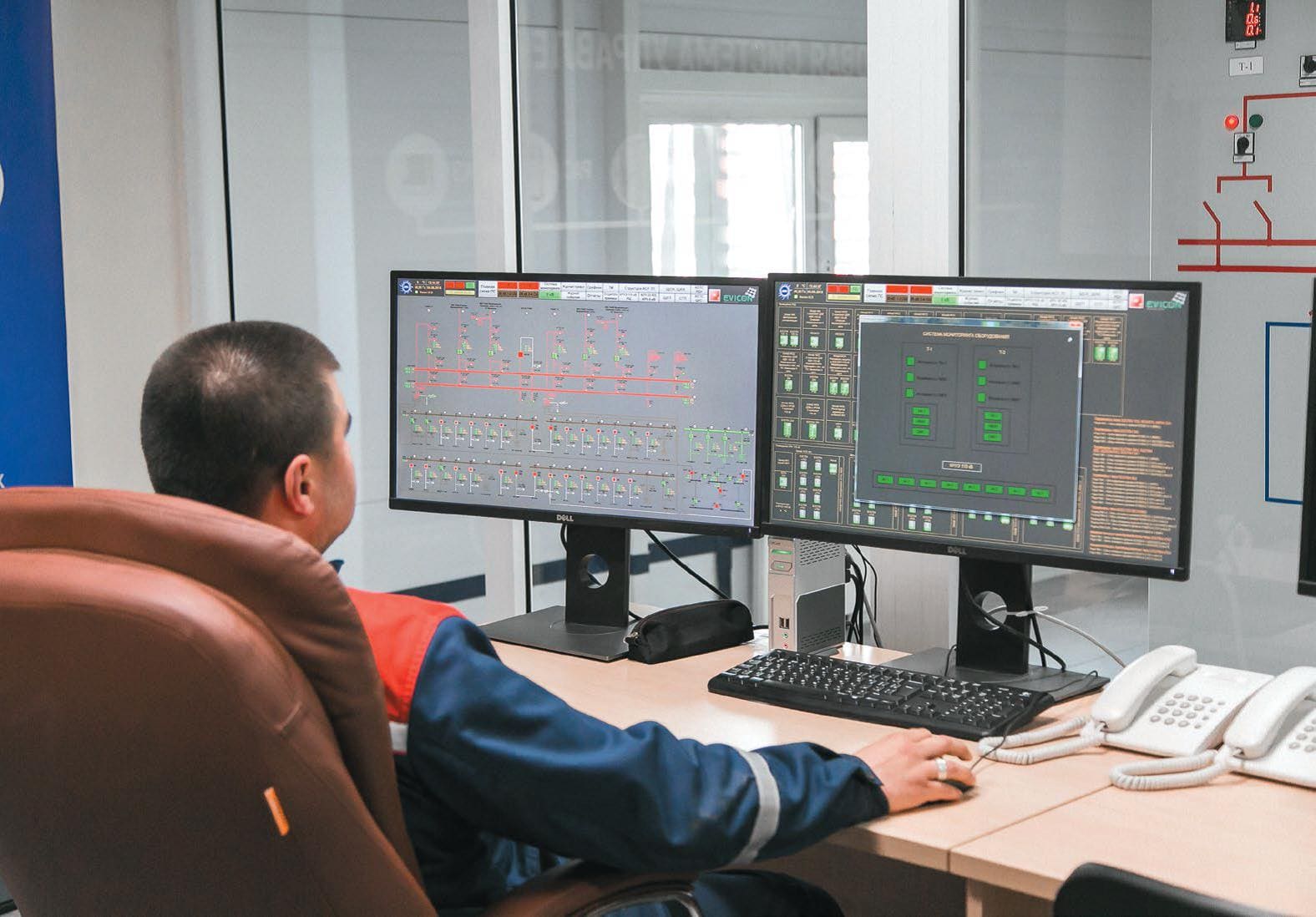
5. Control from a Network Control Center
In the present period, all utility companies have used remote control systems, which has resulted in a decrease in the number of manned substations. Consequently, this has led to a reduction in the workforce and operational expenses. Currently, substations are often unstaffed, and the control function is executed from a central control center that also receives information from and manages multiple other substations.
This is accomplished through the utilization of a “Supervisory Control and Data Acquisition” system (or shorten SCADA system).
An “RTU” or remote terminal unit delivers essential information from each substation to the area control center, allowing for a comprehensive understanding of the monitored network. Additionally, it facilitates the transmission of directives from the area control center to the substations.
The procurement of energy and the ideal layout of the power transmission network in large networks with several area control centers are overseen and supervised by a load dispatching center. This center receives information from power plants, area control centers, and other sources.
In addition to its use in network control, information from the substations is crucial for maintenance and for specialized relay personnel to monitor relay protection. Therefore, there is a requirement for enhanced transmission of information, which can be delegated to various centers based on their category.
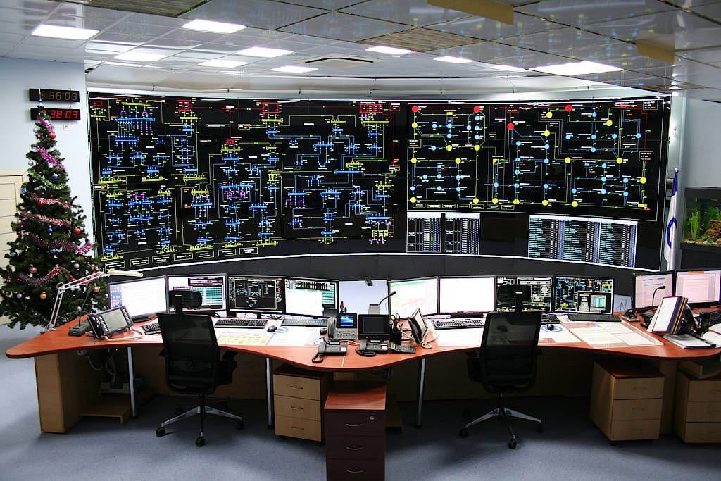
Figure 8 – Electrical network control center
6. Architectures of Control Systems
During the process of selecting the architecture for the control system, it is important to take into consideration the following factors:
Factor #1 – Dimensions and design of the substation, maximum voltage, and planned expansion:
- Size and area
- Indoor or outdoor
- AIS or GIS (air-insulated or gas-insulated substation)
Factor #2 – Manning of substation:
- Manned
- Unmanned
Presently, the majority of substations are designed to operate without personnel. At times, a utility company may choose to run a substation with staff present for various reasons, including:
- Keeping up with the usual useful practice
- Technical reasons (for example, HV equipment and/or communication lines for remote controls that don’t work well)
Factor #3 – Determination of secondary system functions to be incorporated
Factor #4 – Technology of protection and control subsystems
- Old school (traditional)
- Computer-based
Factor #5 – Projected total cost of ownership, which consists of:
- Investment,
- Training, education, and operation,
- Maintenance.
In addition to the needs for availability and dependability that the transmission network and the energy consumer have, the characteristics that have been discussed above should be taken into consideration in great detail. These factors serve as a foundation for the decision-making process about the architecture of the control system and the protection that is linked with it.
Download Guide (PDF) – Design, testing, and commissioning of an IEC 61850-based substation automation system
Design, testing, and commissioning of an IEC 61850-based substation automation system
7. The Need For Substation Extension and Modification
There are a variety of causes that could lead to the extension or modification of substation secondary security systems:
- It is necessary to procure additional primary bays.
- The configuration of the substation has been changed.
- The primary equipment is being replaced.
There is an installation of additional secondary equipment, such as busbar protection or remote control, for example.
The typical control building is divided into two distinct functional areas, which can be classified as follows: maintenance and operations:
- The area that is not reliant on the size of the substation (for example, service areas related to staff)
- The space depending on the size of the substation (for example, the relay room)
It is important that the component that is dependent on the size of the substation has the capability to accept any extensions or alterations that may be foreseen with reasonable certainty.
Good Reading – How to convert an old substation into a digital substation?
8. Minimizing Undesirable Operations in the Control System
Historically, the primary focus about undesired operations was from electromagnetic interference. Compliance with EMC regulations is crucial for all utilities. Currently, there are comprehensive international standards that thoroughly address this topic. Additionally, a significant amount of knowledge and skill has been acquired in the area of cable screening and earthing practices to minimize the likelihood of malfunctions.
Moreover, the growing utilization of fiber optic cables for inter-bay communication has also diminished this risk.
Ensuring the protection of control systems software against intrusion by hackers is increasingly crucial.
Good Reading – Should we be concerned about the cybersecurity of modern digital substations?
Should we be concerned about the cybersecurity of modern digital substations?
9. Interlocking Systems
Many utilities utilize interlocking systems to guarantee the proper sequence of operation for disconnectors, fixed earthing switches, and circuit breakers (when necessary). This ensures that operators do not compromise the integrity of the transmission system by mistakenly or unintentionally operating equipment.
The prevalent situations encompassed by interlocking schemes are:
Condition #1 – Interlocking mechanisms are employed between disconnectors and circuit breakers to prevent the interruption or connection of load currents by the disconnectors.
Condition #2 – The interlocking mechanism between disconnectors and earth switches guarantees that earth switches cannot be closed onto circuits that are locally energized. Similarly, earth switches cannot be energized when closed by the closing of a disconnector.
Condition #3 – The interlocking mechanism allows the disconnector to be engaged for maintenance purposes only when the adjacent earth switches on both sides are closed.
Condition #4 – In order to guarantee that the switching operations for on-load transfers are carried out in the correct sequence at multiple busbar substations and that there is a parallel path between the disconnectors that are attached to each bar.
Condition #5 – To guarantee that a bus coupler or bus section circuit breaker can only be closed when the disconnectors on each side are either both closed (in an operational condition) or both open (in a maintenance condition), the circuit breaker must be in the operational condition.
Condition #6 – To prohibit access to portions of a substation where safety clearances may be violated (for example, filter equipment), unless suitable safety precautions have been implemented, such as isolating the area and earthing it.
In situations when the switching sequences solely include operated switchgear, it is common practice to use electrical techniques to accomplish the interlocking. If everything goes according to plan, the right interlocking status ought to be automatically checked whenever an operation is started, regardless of whether the operation is being started by an operator or as part of an automatic sequence.
Interlock Scheme Example
Incomer Circuit Breaker and Earth Switch Interlocking
The incomer circuit breaker (Q-IL or Q-IR) and earth switch (E-IL or E-IR) are mechanically interlocked to prevent both being closed at the same time. The earth switch can only be closed once the circuit breaker is open and racked-out to the test position. The circuit breaker can only be racked-in for closing, once the earth switch is open.
An additional level of interlocking is required. The incomer earth switch cannot be mechanically operated until power is removed from the incoming supply. This prevents closing the earth switch onto a live supply.
This interlocking is achieved in one of two ways:
Way #1 – Mechanically by using key access. The incomer earth switch (E-IL or E-IR) handle operation is only accessible by using a key, retrieved from the upstream circuit breaker when it is open and racked-out.
Way #2 – Electrically by using a solenoid. A solenoid is energized when the upstream circuit breaker is open and racked out, allowing access to the incomer earth switch (E-IL or E-IR) handle operation.
Figure 9 – Interlock scheme example: Incomer circuit breaker and earth switch interlocking

While it is possible that it will be necessary to bypass an interlock during an automatic switching scheme on occasion, it is important to note that this should be the exception rather than the rule.
In situations when the switching sequence involves plant that is operated manually, the interlocking could be accomplished using either electrical or mechanical components. In an ideal scenario, the interlocking should be designed in such a way that it instantly verifies the status of the interlocking before any operation is performed. When it is feasible, interlocking schemes should allow for the greatest possible operational flexibility and should not impose predetermined working sequences, unless it is absolutely necessary to do so.
The schemes should be intrinsically fail safe, and it should be impossible to defeat them unless one makes use of tools or a facility that is specifically designed to override them.
In general, such override facilities ought to be lockable with a lock that is distinct from the others. Interlocking should be effective for switching and operating sequences when they are followed in either direction (for example, if an earthing switch needs to be closed before an access gate can be opened, then the gate needs to be closed and locked before the earth switch can be opened). Interlocking should also be effective for switching sequences.
Mechanical interlocking is typically accomplished through the utilization of key-operated systems. It is recommended that the keys have a design that is not capable of being mastered. This means that there should not be any master keys, nor should it be feasible to produce a master key with the current design.
At the same substation location, the differs (Note: differ is the name for the difference in a key that prevents it from being interchangeable with another) should not be repeated by users. Typically, an identifying reference that is specific to the location is carved on the interlocking keys by the staff. During normal operation, the key is typically positioned in a certain location, and the key locations are typically identified with the identifier of the associated key.
The identifier would typically comprise the system number of the switching device where the key is typically located.
Good Reading – Learn how to interpret interlocking schemes between MV cubicles (single line and wiring diagrams)
Learn how to interpret interlocking schemes between MV cubicles (single line and wiring diagrams)
There is a possibility that key exchange boxes will be required for more complex interlocking schemes. These boxes ought to be situated in areas that are convenient for the substation to operate normally. Electromechanical key exchange boxes, which offer a connecting up of the electrical interlocking and the mechanical interlocking for a circuit, may be required periodically. These boxes are used to exchange keys.
Historically, the process of electrical interlocking has been accomplished by the utilization of hardwired contact logic. Therefore, it is easy to develop some software logic in order to carry out the interlocking function when using computerized control systems because the state of all of the plant is already known within the control system.
Usually this will involve building a mimic of the entire revised substation in the factory to test the modified interlock software before loading it onto the actual computer system on site.
10. Synchronizing and System Stability
It is necessary to perform synchronization on transmission networks in order to guarantee the maintenance of system stability, reduce the amount of damage accomplished to plant, and make it easier to re-parallel a split system. When circuit breakers are closed when the systems on either side are not in synchronism, a shock load can be imposed on generators, and a significant amount of synchronizing power will flow on the network.
This has the potential to cause a significant amount of disruption.
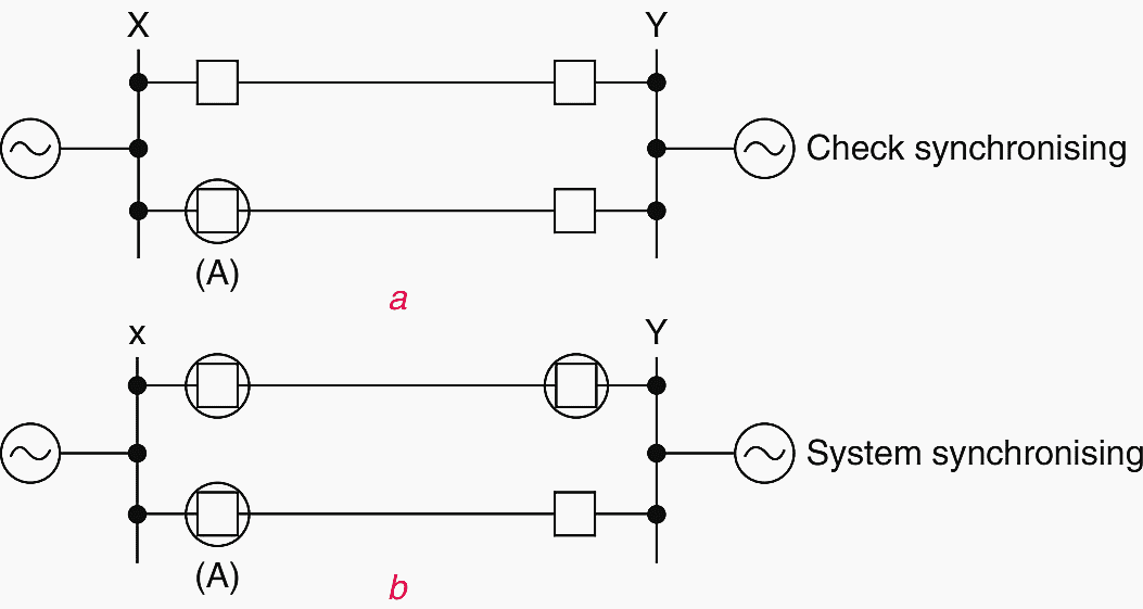
When it comes to the transmission network, the two forms of synchronizing that are typically utilized are check synchronizing and system synchronizing (refer to Figure 10). Check synchronizing is typically the case when the circuit breaker that is being closed is located within a system that is solidly connected, whereas system synchronizing takes place when the circuit breaker that is being closed is connecting two systems that are not connected simultaneously.
Figure 10 – Example showing check synchronizing and system synchronizing (Note, the circled ones indicate the CBs are open)
For a synchronized close to occur, the following requirements must be met:
- Both sides of the CB have the same frequency, which is referred to as zero slip.
- Additionally, there is no phase angle variation between the voltages on both sides of the CB.
- Both sides of the CB have the same magnitude of voltage, which is approximately equivalent to the nominal value
Referring to Figure 11, the synchronizing relay will determine whether or not these conditions are satisfied within a predetermined range of tolerance.
Figure 11 – Synchronizing relay connections and comparison of incoming and running voltages for synchronizing
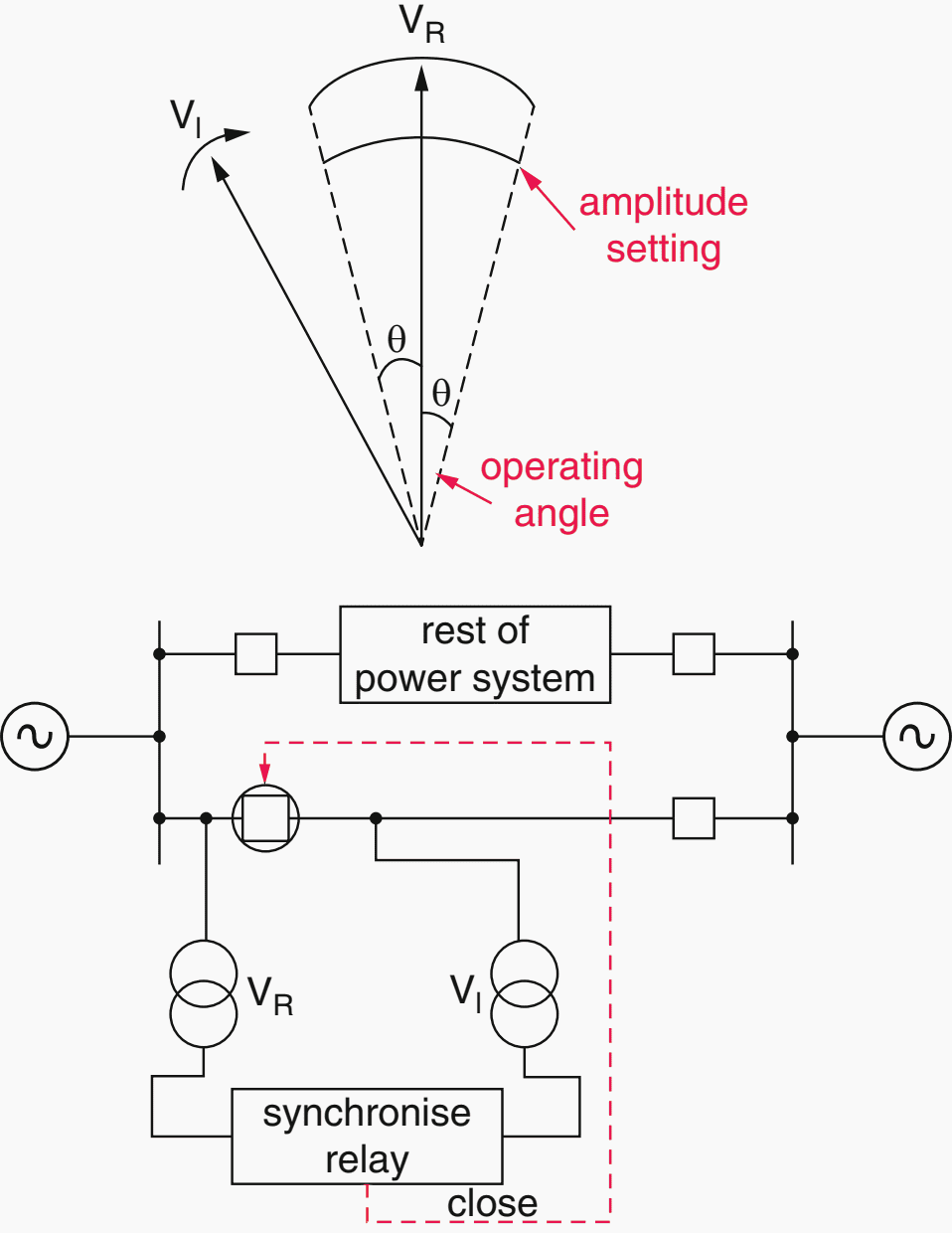
In most cases, there will not be any voltage transformers installed on the busbars. Accordingly, a voltage selection scheme will be necessary in order to acquire the voltage of the busbar in order to establish a “running” voltage.
Because the absence of a voltage will be interpreted as a dead bar or a dead line, it is important to highlight that the output of the voltage transformers should be monitored (for example, by an MCB). A voltage selection scheme, an analogue synchronizing screen that would display the running voltage, the incoming voltage, and a synchroscope that would indicate the instantaneous angle between the two voltages were among the components that comprised the synchronizing system in the past.
In order to achieve a “lamps-light” or “lamps-dark” kind of synchronization, these instruments were occasionally supplemented with lamps.
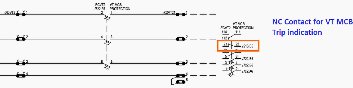
Referencing Figure 12, which illustrates the MCB and its auxiliary contacts connected alongside the main contacts, here’s how this system works:
Figure 12 – Schematic Diagram of VT Miniature Circuit Breaker with Auxiliary Contacts
It is also possible to utilize a synchronizing relay in order to perform a check on the voltages, angle, and slip of this relay, as well as the contacts of this relay that are linked in series into the closing circuit of the circuit breaker. In order to ensure that manual and automatic switching are in sync with one another, this synchronizing mechanism would be essential.
Because computerized control systems “know” all of the necessary information to determine an appropriate running voltage, there is no longer a requirement for a separate voltage selection scheme for synchronization. This is because the computer control system has become more advanced.
To enable manual closing of the circuit breakers, it is also possible to design appropriate software that will allow all of the necessary inspections to be carried out within the computer control system. Any of the following conditions will typically result in the circuit breaker being activated to close the circuit:
- Dead bar/dead line
- Live bar/dead line
- Dead bar/live line
- Live bar/live line (with check synchronizing or system synchronizing as appropriate)
The synchronization check function is typically incorporated into contemporary numerical auto-reclose relays (also known as auto-reclosing) in order to facilitate automatic closing.
Great Reading – The art of generator synchronization techniques that every true engineer MUST know about
The art of generator synchronization techniques that every true engineer MUST know about
11. BONUS! A Guide To Power System Protection For Relay Designers (PDF)
Download BONUS: Download Guide To Power System Protection For Relay Designers (345 pages, PDF) (for premium members only):
Reference: Substation Control and Automatic Switching by John Finn (Cigre)
Related electrical guides & articles


Edvard Csanyi
Hi, I'm an electrical engineer, programmer and founder of EEP - Electrical Engineering Portal. I worked twelve years at Schneider Electric in the position of technical support for low- and medium-voltage projects and the design of busbar trunking systems.I'm highly specialized in the design of LV/MV switchgear and low-voltage, high-power busbar trunking (<6300A) in substations, commercial buildings and industry facilities. I'm also a professional in AutoCAD programming.
Profile: Edvard Csanyi

Very good informative.
Thank you, Qaiser.
Very interesting and useful information.
Very good & also Informative
so good