
Estimated Study Time: 21 minutes
Substation in data center
A few years ago I participated in an interesting project Telenor Data Center in Belgrade – The most advanced technical building in the region of Central and Eastern Europe. The building extends to 2,600 square meters and has the most advanced substation.
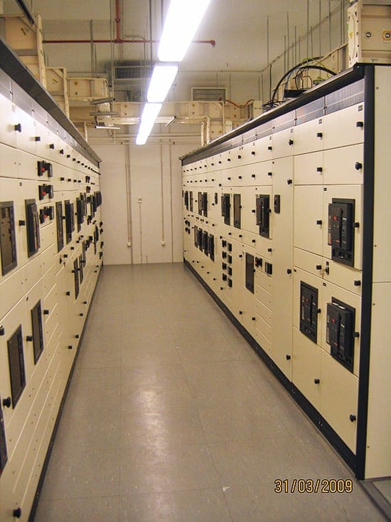
 8 substation equipment needed to power up data center (on photo: Low voltage switchgears type OKKEN; credit: Edvard Csanyi)
This article relies on Pearl Hu’s (APC) white paper and it describes the equipment that was installed in the substation and without which it would not be possible to operate the data center.
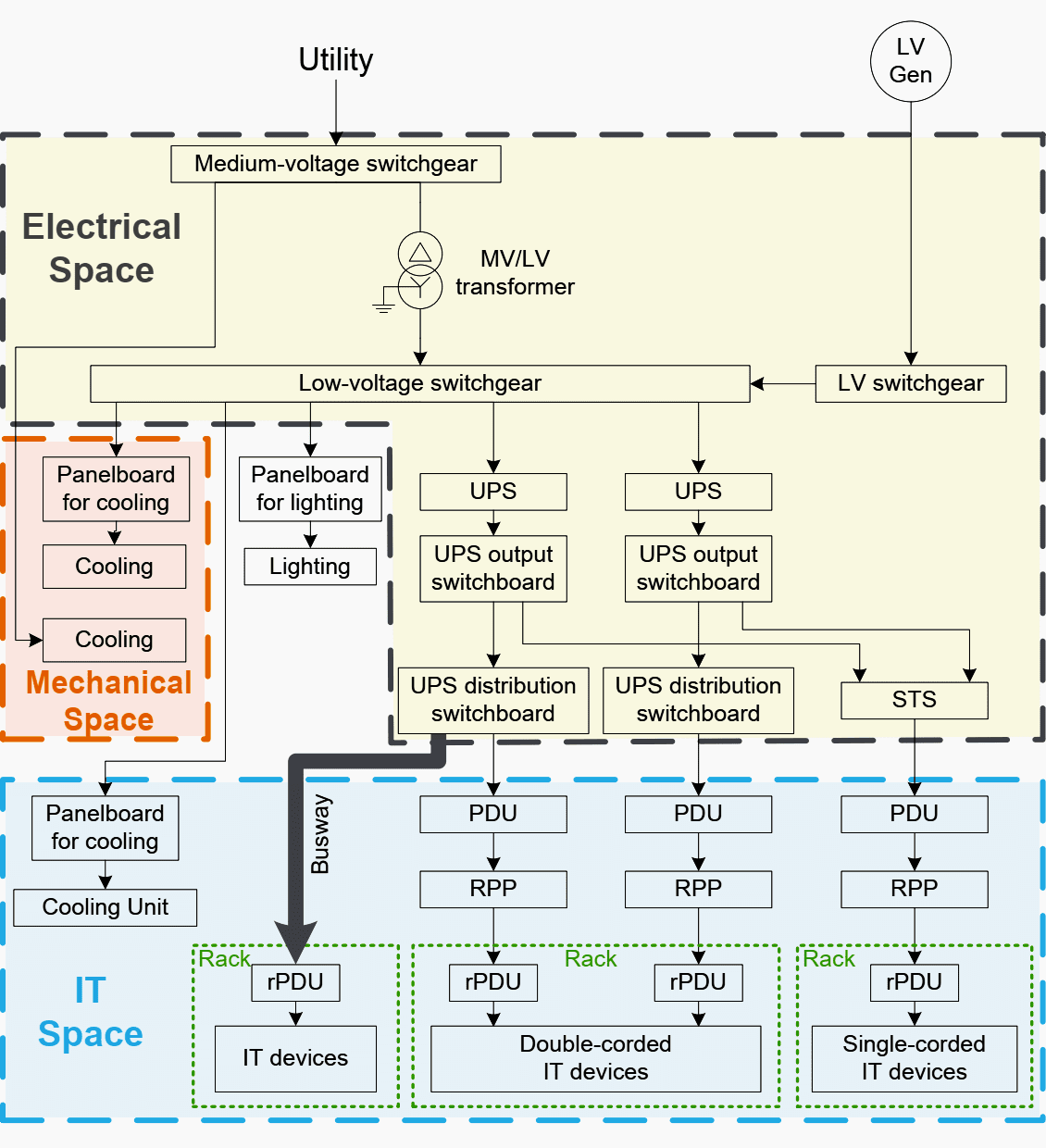
There are many different loads in the data center, such as IT equipment, air conditioners, fans, pumps, lighting, etc. The flow and transformation of energy from the utility/generator to the load is enabled by various types of equipment.
Tracing the flow of energy along its path (starting from the utility to the IT loads) in Figure 1 illustrates the following types of equipment:
- Medium-voltage switchgear
- MV/LV transformer
- Low-voltage switchgear / switchboard / automatic transfer switch (ATS)
- UPS system with input/output switchboard and UPS distribution switchboard
- Power distribution Units (PDUs) and remote power panels (RPPs)
- Busway
- Panelboard
- Rack PDUs (rPDUs) / outlet strips
All the equipment in the list above, except for rack PDUs (rPDUs), are considered to be assemblies containing circuit breakers, switches, various types of relays, buses and connections, and control and auxiliary devices.
The IEC 61947 & IEC 62271, which specifies the HV and LV switchgear terminology, considers switchboard to be the same as switchgear. While in North American, switchgear and switchboard are specified differently by ANSI and UL standards.
The following subsections introduce each type of equipment.
1. Medium-voltage switchgear
Medium-voltage switchgear is generally located in the power substation of large-capacity data centers (i.e. greater than 1 MW IT load). This equipment is typically fed directly from the utility and usually marks the utility service entrance to the building.
If a MV generator is present, it also feeds the MV switchgear. Figure 2 shows an example of MV switchgear single line diagram.
Other than simply distributing power, the MV switchgear is responsible for disconnecting faults and controlling the MV power distribution system, for example, when isolating a redundant section for maintenance.
Basically medium-voltage switchgear is the assembly of the following four cubicles as shown in Figure 3: two incoming units (incomers) or main section, outgoing units or feeder section, voltage metering unit, and bus section or tie section/breaker.
All circuit breakers in this example are motorized.

The outgoing unit distributes three-phase power to the primary (upstream) side of the MV/LV transformer. Due to safety distances at MV, typically each cubical is limited to only one MV circuit breaker.
The following are some typical electrical parameters for MV switchgear. Values for these parameters vary according to local regulations:
Voltage ratings:
Two key voltage ratings for MV switchgear are rated voltage and rated lightning impulse voltage (equivalent to the ANSI basic impulse level i.e. BIL). For example, an ANSI MV switchgear solution may have a rated voltage of 15kV and 95kV BIL (i.e. impulse voltage).
Current ratings:
The rated current of MV switchgear is always specified by the manufacturer. Another key current rating is the rated short-circuit withstand current similar to the North American National Electric Code’s (NEC) short-circuit current rating (SCCR).
For example, an ANSI MV switchgear solution may have a rated current of 1200A and 40kA SCCR.
2. MV/LV transformer
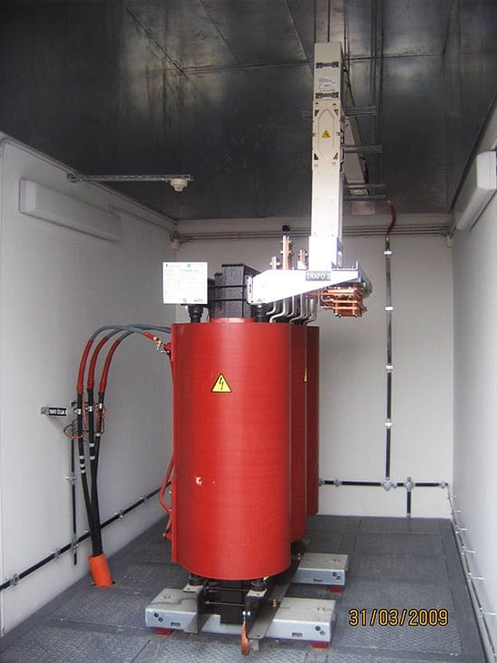
Dry type transformers, with and without an enclosure shown in Figure 4, are installed in transformer rooms inside power substation to step down medium voltage from the MV switchgear to low voltage for the downstream power distribution equipment.

The key electrical parameters of MV/LV transformers include: rated power (i.e. 2500kVA), primary and secondary voltage (i.e. 10kV/400V), and impedance (similar to resistance) specified as %Z (i.e. 5%).
Generally, transformer can be with or without enclosure (IP00 or IP31).
3. Low-voltage switchgear/switchboard / automatic transfer switch (ATS)
Typically LV switchgear/switchboard is located in the electrical room and marks the utility service entrance for data centers less than 1 MW.
An example of LV switchgear is shown in Figure 6 and Figure 7. If a LV generator is used, the generator would feed the LV switchgear. Apart from distributing power, the LV switchgear is responsible for disconnecting faults and controlling the LV power distribution system.
Note that in the case of a medium voltage generator, this transferring function occurs at the medium voltage switchgear level.

In reality, this single line diagram will look something like this:
LV switchgear/switchboard installed in a data center is typically a combination of some of the following functional units: incoming feeder from the secondary side of the MV/LV transformer or LV generators, power control center (PCC, i.e. for downstream UPS), motor control center (MCC, i.e. for pumps), the power factor correction/harmonic filtering and the bus connections.
The following devices are always assembled in LV switchgear: horizontal busbar, vertical busbar, circuit breakers, meters, switches, surge arresters, relays, etc.
The following are the key electrical parameters of the LV switchgear. The values for these parameters vary according to local regulations:
Voltage ratings:
Two key voltage ratings for LV switchgear are rated voltage and rated lightning impulse voltage. ANSI does not specify the impulse voltage for LV switchgear. For example, an IEC LV switchboard solution may have a rated voltage of 690V and 12kV rated impulse withstand voltage.
Current ratings:
The rated current of LV switchgear is always specified by the manufacturer. Another key current rating is the rated short-circuit withstand current similar to the North American National Electric Code’s (NEC) short-circuit current rating (SCCR).
For example, an IEC switchgear solution may have a rated current of 5000A and 85kA rated short-circuit withstand current.
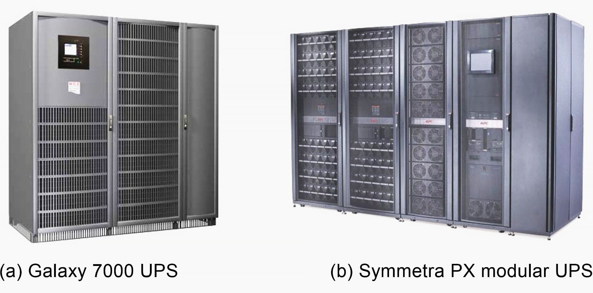
4. UPS
UPS systems are typically installed in the electrical space or IT space of the data center to provide uninterrupted power to the critical equipment it supports. The UPS design configuration chosen directly impacts the availability of critical IT equipment.
There are various types of UPSs available, depending on the application. Some examples of UPSs are shown in Figure 9.
The following devices are typically installed inside UPSs: input/output switches, bypass switches, static switches, power modules including the rectifiers and inverters, and their control and communication modules.
Depending on the size of data center and system’s availability requirements, UPS configurations include some of the following electrical equipment: UPS, UPS input switchboard, UPS output switchboard, UPS distribution switchboard, and static transfer switch (STS) for bypass.
Depending on the design architecture and business requirements, the three following types of LV equipment may be located along side of the UPS in the electrical room.
The UPS input switchboard feeds to UPS from power control center of the upstream LV switchgear/switchboard as shown in Figure 10(a).
While the UPS output switchboard, as shown in Figure 10(b), not only provides the power from UPS output to the downstream circuits, but also consists of the static bypass circuit breakers and maintenance bypass circuit breakers to allow utility power to clear faults or isolate the UPS for maintenance.
In some cases, isolation transformers are installed in the input or output switchboard as well. See White Paper: The Role of Isolation Transformers in Data Center UPS systems, for more information on this topic.
The three LV switchboards above typically include the incoming feeder, the outgoing branch circuit, and the bus connection.
UPS input/output switchboard and UPS distribution switchboard can be provided by the UPS supplier as optional accessories. It can also be provided by switchgear/switchboard vendors.
Data Center UPS system 960kVA
5. Power distribution Units (PDUs) & Remote power panels (RPPs)
Traditional PDUs and RPPs are located in the IT space to distribute, control, and monitor the critical power from the upstream UPS system to IT racks.
PDUs usually contain a main input circuit breaker, branch circuit panelboard(s), a power transformer, output power cables, surge arrestor, and the monitoring and communication modules.
Sometimes PDUs with power transformers can generate a new “grounded” neutral for the downstream IT loads.
In North American data center PDUs with power transformers are mainly used to step down 480 Vac to 120/208 Vac8, while in Japan, PDUs with power transformers step down 200Vac to 100Vac single-phase for the downstream IT loads. A PDU is typically rated from 50kW to 500kW.

A switching device, called a Static transfer switch (STS), is sometimes integrated into the PDU cabinet located in the IT space or is also available as stand-alone cabinets located in the electrical space.
Referring to Figure 1, an STS has two inputs from the UPS system and one output to the downstream PDU.
Remote power panels (RPPs) are like PDUs without a transformer and are therefore smaller, having a footprint about the size of a standard 2’x2’ raised floor tile. RPPs may contain up to four panelboards and a monitoring system, and distribute power to the IT racks.
RPPs are most often fed from one or more PDU sub-feed breakers.
6. Busway
Busway is an alternative to traditional power distribution using PDUs and RPPs (see Figure 1 above).
Busway usually includes the feed unit connected with an upstream LV electrical switchboard, the power bus, the plug-in units or tap-off unit equipped with the over-current protection devices, the connection fittings and their accessories.

One real example of busway with 2N redundancy mounted overhead in IT space is shown in Figure 12. Generally, busway can be mounted under floor in the IT space as well.

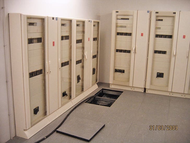
7. Panelboard
Panelboards (typically rated from 1.5kVA to 75kVA) are basically a metal cabinet that house the main electrical bussing and the terminals upon which circuit breakers, neutral wires, and ground wires are installed.
Panelboards are common in the mechanical space, electrical space, and IT space to distribute the power to cooling equipment (i.e. chillers, pumps, fans, etc.), lighting, and security devices. They are typically mounted against a wall or on steel bracings and are accessible only from the front as shown in figure 13.
Generally speaking, the term panelboard is market nomenclature for wall-mounted LV switchboard.
In data centers, panelboards are sometimes used in place of, or in combination with, RPPs. However, in most cases, the panelboards are assembled in a cabinet like PDUs and RPPs to distribute the power to the IT racks.
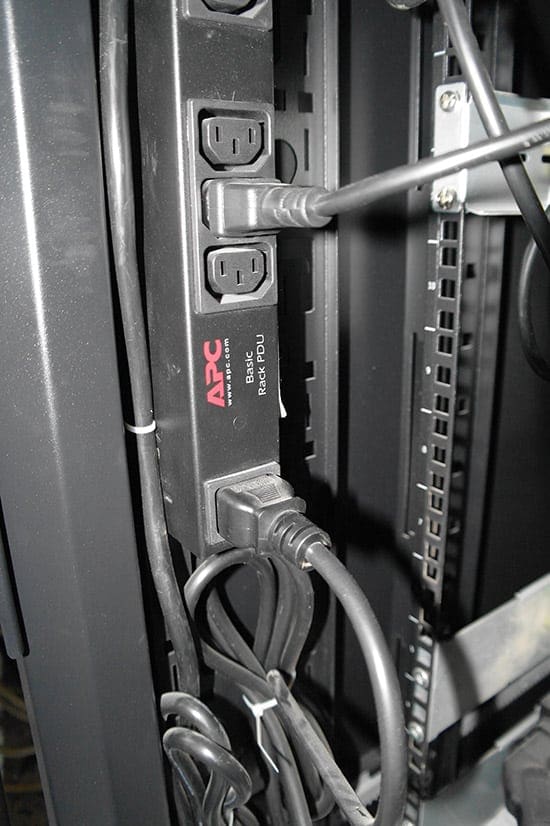
8. Rack PDUs (rPDUs) / outlet strips
Rack PDUs (i.e. power strips) are installed in IT racks and are powered from the mating connector of the upstream PDU or RPP and distribute power directly to IT equipment in the rack.
Three-phase rPDUs or one-phase rPDUs are selected based on the expected rack power density and or system configuration.
Metered rack PDUs provide real-time remote monitoring of connected loads. User-defined alarms warn of potential circuit overloads before critical IT load drops.
Switched rack PDUs provide advanced load monitoring combined with remote on/off switching control of individual outlets for power cycling, delayed power sequencing, and outlet use management.
Different names are assigned only for market nomenclature or through habit.
Though Figure 1 presents one example of the data center architecture to cover the possible electrical equipment, some of the common differences / variants are mentioned below:
- MV generator can replace the LV generator as the backup energy source feeding the MV switchgear.
- UPS systems may be located in the IT space or in the row of IT racks for smaller data centers.
- PDUs can distribute the power to the IT racks directly thereby avoiding the use of RPPs.
- STS can be integrated in the PDU cabinet to provide distribution redundancy.Rack-mounted automatic transfer switches can be another solution to provide the redundancy.
- Cooling units in the IT space can be fed by the UPS if continuous cooling is required during a power outage.
- Busway alone can provide all LV power distribution from the LV switchgear/switchboard to IT racks.
- UPS input power can be derived from the LV switchgear/switchboard directly to the UPS thereby eliminating the need for an input switchboard.
- The UPS output switches and distribution switches may be assembled in one LV switchboard.
- An integrated UPS system may include the input, output, or distribution switchboard.
Generally the data center architecture depends on the data center capacity, the system redundancy, the IT racks arrangement, and the equipment providers etc.
Reference // Electrical Distribution Equipment in Data Center Environments by Pearl Hu at Schneider Electric
Related electrical guides & articles


Edvard Csanyi
Hi, I'm an electrical engineer, programmer and founder of EEP - Electrical Engineering Portal. I worked twelve years at Schneider Electric in the position of technical support for low- and medium-voltage projects and the design of busbar trunking systems.I'm highly specialized in the design of LV/MV switchgear and low-voltage, high-power busbar trunking (<6300A) in substations, commercial buildings and industry facilities. I'm also a professional in AutoCAD programming.
Profile: Edvard Csanyi

I will much delighted to receive more info related to Data Center
I was asked to prepare a series of articles for Vertiv Data Center Solutions similar to this as a training tool for new hires.
I found this article an excellent resource and will cite it in the the additional references section along with two other links.
Nice article. But there are also many weaknesses. There are many “hot” places, which makes the system difficult to repair.
Excelente información saludos!
Very usefull information!
This very interesting ill like to hear more I am Electrician but self Employed
Very good
The info is indeed helpful and had substance to boost and individuals technical skills .More so for new graduate who just started working at power plant and substation .
I will be much delighted to receive more information about designing a substation distribution station
It’s good imformation