
Estimated Study Time: 8 minutes
DC voltage 110 V or 220 V
A power substation can have one or several DC systems. Factors affecting the number of systems are the need for more than one voltage level and the need for duplicating systems. Today, normal DC auxiliary supply systems in power substations are operating either on the 110 V or 220 V level, though lower levels exist.
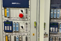
 Substation DC Auxiliary Supply - Battery And Charger Applications (on photo: Newly completed DC auxiliary power supply of substation in Naramata BC; credit: Paul Chernikhowsky via Flickr)
Some systems at the substation may require lower voltages as their auxiliary supply source.
A typical example of these systems would be the optical telecommunication devices or the power line carrier (PLC) equipment, which normally requires 48 V. If the power consumption of these devices is low enough, their supply can be arranged with DC/DC converters, supplied by the higher voltage level DC system.
Elements of DC Auxiliary System
Single-battery and charger application
The main components of the system are the battery, charger, and distribution switchboard including the DC system monitoring relay. Figure 1 shows the mainline diagram of a single battery and charger application.

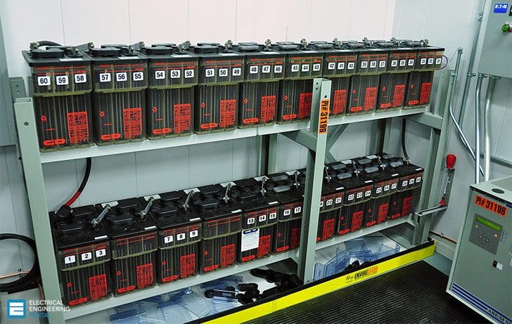
In a typical installation, especially with batteries of considerable size, the batteries are installed in a separate battery room. The ventilation of the battery room shall be adequate, considering the type and size of the battery. The temperature level in the battery room should not exceed 25°C, since temperatures above this significantly affect the lifetime of the battery.
The charger and distribution switchboard are normally located in the same room, separate to the battery.
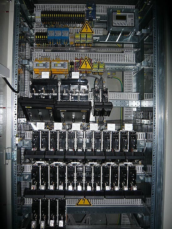
The main fuses are supervised and an alarm is given in a case of a blown fuse (Figure 2). If the main fuse (F1 or F2) is blown, the overcurrent tries to divert its path via paralleled miniature circuit breaker (F1.1 or F2.1). This miniature circuit breaker has a very small rated current and is also tripped immediately, causing the alarm contact 95-96 to close.

The cables leading from the main fuse boxes to the distribution switchboard are run separately for both polarities with at least a 10 cm distance between each other. The cables are installed in non-conductive (plastic) pipes for the total length.
Usually at the distribution switchboard there is provided a separate fuse switch output for connecting external battery discharger equipment, as shown in Figure 1. This output can be utilized while making a battery discharge test during substation commissioning or regular maintenance and testing.
Duplication of the system
Relay protection, control, and interlocking circuits
Since the DC system supplying specially relay protection, control, and interlocking circuits is of paramount importance to the substation’s reliable and safe operation, the energy supply has to be always available. The need for this reliable supply becomes even more important during disturbances and faults in the high- or medium-voltage primary circuits.
The importance of this reliable DC-auxiliary power is crucial for the substation as such. The higher (more important) role the substation plays from the complete distribution or transmission network point of view, the higher are the demands for the substation’s DC auxiliary power systems.
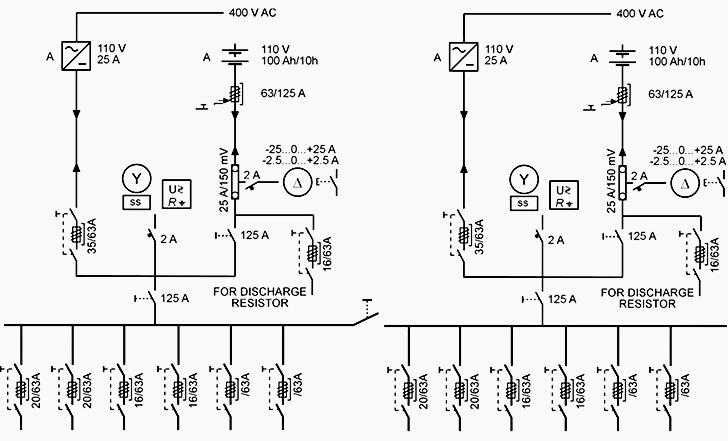
To meet the increased demands for reliability and availability, the DC system can be doubled (Figure 3). This means that there are two separate systems, at the same voltage level, running in parallel. Both of the systems have their own batteries and chargers.
The distribution switchboard is divided into two separate sections, where both battery and charger sets are supplying their own sections.
There is a bus tie switch connecting the busbars of the different sections together. Under normal conditions, this bus tie switch is kept open. In case of faults or maintenance on one of the battery and charger sets, the bus tie can be closed, thus enabling the other battery and charger set to supply the whole load.
The actual circuits that the doubled DC system is supplying are distributed equally among the two sections in the switchboard. Circuits with doubled functions, like trip circuit 1 and trip circuit 2, are connected to separate sections. This way, the fault in one of the sections does not affect the tripping circuits connected to the second section.
This means that for example with the circuit breaker there should be two separate tripping coils, one for trip circuit 1 and the second one for trip circuit 2. The cabling for these two circuits (tripping coils) should be done with separate cables utilizing, as far as possible, also different cabling routes.
Furthermore, a common practice is that the main protection relays receive their auxiliary supply from as well as give their trip commands to trip circuit 1, whereas the backup protection relays utilize trip circuit 2 for the same functions. The local and remote circuit breaker control functions (opening command) typically utilize trip circuit 1.
Reference // ABB’s Distribution Automation Handbook – Elements of power distribution systems
Related electrical guides & articles


Edvard Csanyi
Hi, I'm an electrical engineer, programmer and founder of EEP - Electrical Engineering Portal. I worked twelve years at Schneider Electric in the position of technical support for low- and medium-voltage projects and the design of busbar trunking systems.I'm highly specialized in the design of LV/MV switchgear and low-voltage, high-power busbar trunking (<6300A) in substations, commercial buildings and industry facilities. I'm also a professional in AutoCAD programming.
Profile: Edvard Csanyi

What are the options to make a charger failure alarm in a thyristor control charger.
I want to know if there are countries which use Li Ion batteries for dc supply in substations. And what is they behavior. Thank you!
What can cause the main circuit breaker in the switchgear panel to keep failing to discharge when there is a disturbance or faults.
Restoration of DC Battery charger power supply after energization of substation shall be included in the procedure.
Kindly suggest one efficient method for the following requirement.
1) How to monitor each cell voltage from remotely by using SCADA system.
2) How to generate alarm in SCADA if any one of the cell nominal voltage reduced.
What is the best and safe way to change change out one battery in a 60 cell, 2 volts per cell sub/station battery rack
the rectifier is worked normally only self operation with out Battery connection and the battery voltage is 2 v each and total battery is 56 cells,
the battery and rectifier connected for normal operation the rectifier is fluctuated and bus voltage is under signal is come why?
The supply to the auxiliary DC have failed how to start the process of maintenance and rectification . The alarm and other relay circuit also seems to be not working . Kindly give me the step wise process .
Good evening what is possible to happen when DC failed to work in a substations and operation is carried out. Is there going to he an explosion or what??
The relays and associated circuit breakers won’t be able to trip due to the absebse of supply voltage into their operating coils which initiates the relays operation incase of occurance of fault. So yes an explosion may occur when an abnormal condition such a s fault occur in the unprotected zone
Dear Sir,
It is appreciated if you advice us about, which is better solution for battery system in the mobile substation 132/33kV to get 110V DC, using 92 cells with 1.2V or 74 cells with 1.5V?
Best regards
Mahir S. Saleh
2 V * 55 cells is the better operation.
R/Sir,
IN MY WORKING PLEASE USED 110 VOLT DC BATTERY SET BUT CURRENTLY I FACING THE PROBLEM OF CORROSION IN TERMINAL .AFTER CLEANING 3-4 DAY SAME CORROSION HAPPEN . BATTERY IS NEW ONE 3 YEAR OLD .
Could anybody recommend a brand of batteries charger, application is for battery bank who is providing energy to protection devices on medium voltage interrupters
Dear sir,
Please provide pdf of battery charging and discharging cycle calculation and maintenance of battery bank of 150ah.
My mail id is [email protected]
it’s too good for learners
Dear Sir,
I am writing this email on behave of DABS (National electricity company of Afghanistan). DABS is responsible for generation and distribution of energy across the Afghanistan. DABS needs to purchase 220 VDC and 48 VDC battery & battery charger backup system. for further conversation please contact us through below email to share the design and technical specification for your quotation.
Email: [email protected]
Regards
DABS Procurement Team
Sir,
I have send the email for you. Pls kindly check it. thanks
Please check web page from company KONČAR – Electronics and Informatics Inc. who is
leader in manufacturing and delivering of power supply systems in Croatia
http://www.koncar-inem.hr/en/products/energy-2/power-supply-systems/
Dear sir
Please answer the following
1. Some times battery cells develop high resistance. This causes battery bank to not to give energy to the equipment in Substations
2. is there any alternative option for dropping resistar
3. we want online monitoring of battery condition
4. Chargers should be lightning proof and switching transient proff. what IEC standards are required?
best regards
Anwar
SEC Riyadh
0505187252
Thank you for this portal. I am in the Technical training environment and your contribution through this portal is of exceptional value. I do not see myself as a Subject Matter Expert but I have learned and confirmed a lot over the past 30 years in this vast field. Your website have given me frequent info and confirmation on training topics needed. I would like to thank you sincerely for this.
What is load in watts of each relay which gets dc power supply. say over current relay, earth fault relay, percentage difference relay, distance relay, etc. This will helpful in battery sizing.
Dear sir
I need site acceptance test form for battery charger in power substations.
Thank you
Please post an article on Substation Design.
It is much needed.
Thank you
What is the difference between float voltage equalization voltage
Can i use a switch mode power supply which gives DC output voltage, when it is fed with UPS AC supply in case of Battery bank and battery charger.
If I use 125 DC volt charger, what is the maximum voltage tolerance load (trip coils) can accept. ?
What is the recommended backup time for the batteries and sizing…
i want to know what is the use of auxiliary supply in a substation how its works?
As the name indicates that Power supply which cater the substation auxiliary loads.
Auxiliary loads are categorized as critical & non-critical loads.
AC supply used for non-critical loads and DC supply for critical loads as in this article.
The non-critical loads are such as substation lighting, heating, ventilation, small power, CB/isolators operating mechanism etc.
The critical loads are trip coil of CB, protection relays, SCADA, communication devices, emergency lighting etc.
i want to know, what is the use of auxiliary supply in a substation? how it works
Thank you for these good information
Thanks for your technical articles.
could you please do articles on substation design.
I am a project engineer based on substation installation and commissioning