
Estimated Study Time: 22 minutes
The art of substation design
Irrespective of the voltage level and capacity of any substation, the numbers of equipment and their size are usually the major factors in determining the overall capital cost of substations. In this article, we will primarily focus on analytical skills for the selection and sizing of major substation components: cables, busbar, and transformers.
 Guidelines for HV substation designers to properly analyze, size and select equipment
Substations might come with different functionality and sometimes with design life over 40-50 years, which creates confusion for design engineers in selecting design parameters and components.
Normally, the selections are subjective and require holistic analysis to decide what fits the best. Analytically, the design engineer needs to justify each selection, however puny it might be. The best optimal design is usually a trade-off of various affecting factors.
First, let’s discuss them in random order.
- Affecting factors:
- Components sizing/ selection cases
- Analysis and decision making
1. Affecting factors
1.1 Specific functions and requirements of a substation
A common mistake usually seen in substation design is stereotyping. The design engineer must be aware that every substation could be different in function and construction despite similarities to varying extent.
Take, for instance, two 33/11 kV primary distribution substations constructed in adjacent load centres. There is every possibility of those two substations being very similar yet entirely different. While both might be rated at a similar capacity, one could be indoor with a dry-type transformer for bulk load supply whereas, another could be a power utility substation with an outdoor switchyard.
Neglecting the factors like cable routing mediums, ambience temperature, clearance, etc., while selecting the substation components could turn the whole design disastrous.
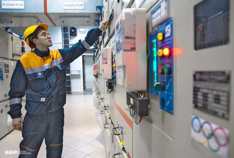
Figure 1 – Routing substation cables
Go back to the Contents Table ↑
1.2 Provision of expansion or capacity enhancements
Despite the extrapolated load profile, the substations sometimes could be subjected to overload sooner than expected and require capacity enhancements which influence the selection of types and number of components.
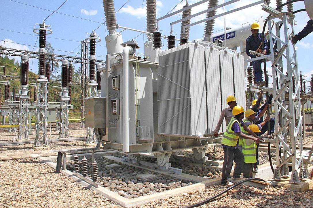
Figure 2 – 33/11 kV distribution substation with spare space on the left side for future expansion
For instance, the design engineer could opt for multiple numbers of small transformers operating in tandem to feed current loads instead of a single large transformer. This allows easy capacity expansion with the addition of extra identical transformers without completely replacing the existing ones.
On the contrary, in the case of a fixed load profile and large switching power grid substations, opting for a single large transformer could be beneficial for easy installation and high-efficiency operation. Thus, this requires the engineer to analyze multiple aspects for each major component. The individual instances shall be discussed further in the dedicated sections below.
Go back to the Contents Table ↑
1.3 Space factor and installation
Space factors usually pose a unique non-technical headache for design engineers while selecting the substation components. This is particularly important in the case of indoor substations and urban substations in tight spaces.
For instance, a particular component might fit well in the design phase but creates all sorts of headaches when it comes to installation in lack of proper technical skills for installation.
These are quite common for a complex setup like GIS substations which require equally sound installation provision (skilled manpower, temperature suitability, etc.) to complement the design part.
Related electrical guides & articles


Bishal Lamichhane
Electrical Engineer (B.E Electrical, M. Sc Engineering) with specialization in energy systems planning. Actively involved in design and supervision of LV/MV substations, power supply augmentations and electrification for utilities and bulk consumers like airports and commercial entities. An enthusiast and scholar of power systems analysis.Profile: Bishal Lamichhane
