
Estimated Study Time: 32 minutes
Equipment Testing Lifecycle
In power systems, reliability is not achieved by design alone. It is established through a structured process of verification, validation, inspection, and testing carried out at different stages of the equipment lifecycle. Whether the equipment is a power transformer, switchgear assembly, protection panel, current transformer, battery charger, or SCADA panel, it must pass through a sequence of formal tests before it can be accepted for service.
 Substation Equipment: From Type Testing to Factory and Site Acceptance Testing (FAT, SAT)
This sequence is commonly referred to as the equipment testing lifecycle. It ensures that the equipment design is technically sound, and the manufactured unit conforms to approved drawings and specifications.
It also ensures that the installed system performs correctly under real operating conditions.
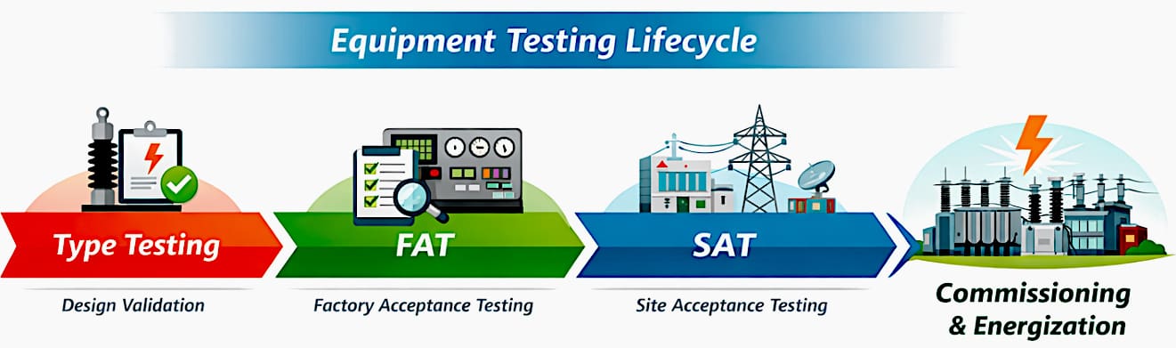
At a high level, the lifecycle consists of three major stages:
- Type Testing: Design validation stage
- Factory Acceptance Testing (FAT): Manufacturing verification stage
- Site Acceptance Testing (SAT): Installation and integration verification stage
Together, these stages form a progressive path from design approval to operational readiness.
Figure 1 – Substation Equipment Testing Life Cycle
- The Concept of the Testing Lifecycle:
- Type Testing – Design Validation Stage:
- Transition from Type Testing to Production
- Factory Acceptance Testing (FAT) – Pre-Delivery Verification:
- Types of FAT Based on Witnessing:
- Core FAT Activities:
- FAT Planning and Preparation:
- FAT Execution – Practical Step-by-Step Approach
- FAT in Modern Substations
- Practical Risks Addressed by FAT
- Utility Perspective – Why FAT Is Taken Seriously?
- Regional Approaches and Key Differences:
- Best Practices for Effective FAT
- FAT Deliverables
- Attachment (PDF) 🔗 Download ‘Factory Acceptance Test Procedure of Low Voltage Switchboards’
1. The Concept of the Testing Lifecycle
Testing lifecycles in power systems is a structured approach that moves equipment from engineering design to real operational service in a controlled and traceable manner. It does not rely on one final test to prove the entire system.
Instead, it uses multiple stages, each with a specific objective.
So, what is the testing lifecycle?
At its core, the testing lifecycle addresses three fundamental engineering questions:
- Is the design technically capable and compliant with standards?
- Has the equipment been manufactured correctly?
- Will the installed system operate reliably in the field?
Each stage answers one of these questions.
1.1 Progressive Validation Philosophy
The lifecycle progresses in a logical sequence:
- Type Testing confirms that the design itself is valid.
- FAT confirms that the actual manufactured equipment has been assembled, wired, and configured correctly.
- SAT confirms that the installed system works correctly when connected to other equipment at site.
This layered methodology is essential in substations because a single-stage testing approach is insufficient for complex systems involving protection, control, SCADA, interlocks, communications, AC/DC supplies, and primary equipment interfaces.
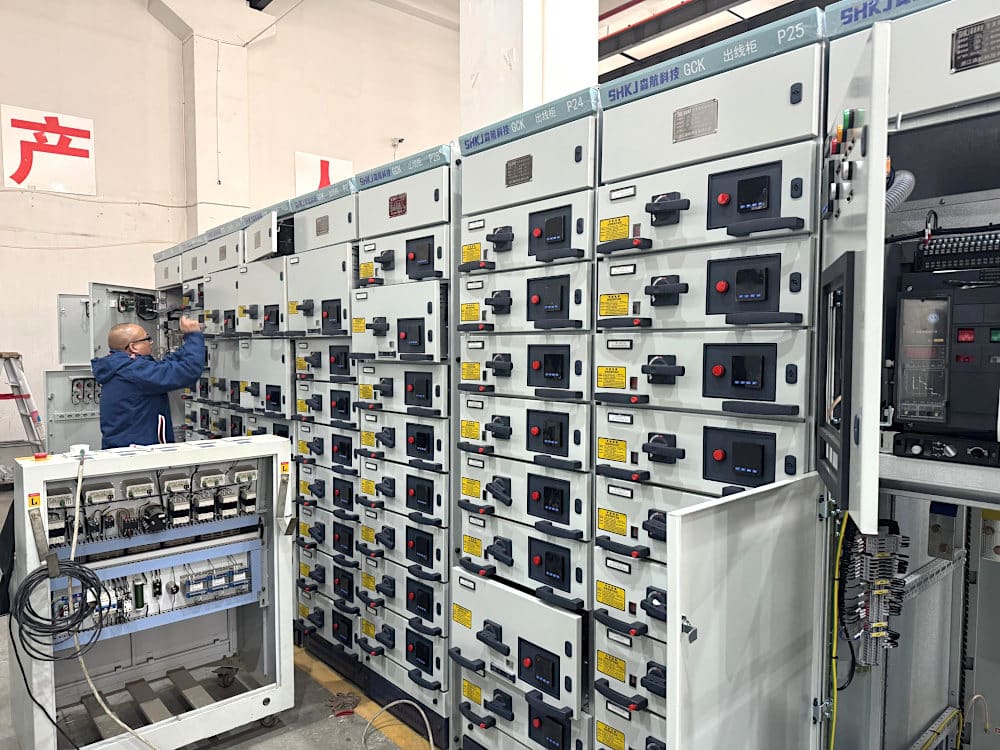
Figure 2 – FAT of newly manufactured 0.4kV withdrawable switchgear
1.2 Why This Layered Approach Matters
Well, there are three main reasons:
- A defect identified during type testing prevents an unsuitable design from entering production.
- A defect identified during FAT prevents a wrongly manufactured panel or piece of equipment from being dispatched to site.
- A defect identified during SAT ensures that integration or installation issues are corrected before energization.
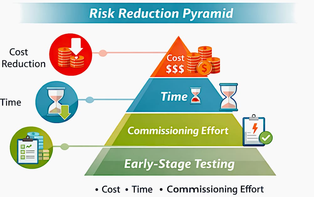
In simple terms, the lifecycle acts as a sequence of quality gates. Problems are identified where they are cheapest and easiest to fix.
Figure 3 – Risk reduction pyramid showing early-stage testing saves time, cost, and commissioning efforts
2. Type Testing – Design Validation Stage
Type testing is the first formal technical validation stage in the equipment lifecycle. It is performed on a representative prototype or sample, not on every manufactured unit.
The purpose is to prove that a specific equipment design meets the requirements of applicable standards such as IEC, IEEE, or utility-specific specifications.
2.1 Purpose of Type Testing
Type testing answers a specific question: Is this design capable of performing safely and correctly under defined electrical, thermal, and mechanical conditions?
2.2 Examples of Type Tests
The type of test depends on the equipment. Let’s list the type tests for switchgear, power transformers, and instrument transformers (CTs and VTs):
For switchgear, typical type tests may include:
- Short-circuit withstand testing
- Di-electric withstand testing
- Temperature rise testing
- Internal arc testing
- Mechanical endurance testing
For power transformers, type tests may include:
- Lightning impulse test
- Temperature rise test
- Short-circuit withstand verification
- Sound level measurement
- Induced overvoltage test
For instrument transformers such as CTs and VTs, type tests may include:
- Accuracy tests
- Insulation performance tests
- Thermal and dynamic withstand tests
- Burden verification
- Knee-point and excitation characteristics
Suggested Tool – Current transformer (CT) saturation calculator
2.3 What Type Testing Does Not Prove?
It’s very important to note that type testing does not guarantee that every unit subsequently produced will be defect-free. It validates the design, not each manufactured product. Once type testing is successfully completed, production can begin, but each manufactured unit must still undergo further verification.
3. Transition from Type Testing to Production
Once a design has successfully passed type testing, it becomes eligible for manufacturing. However, the project risk does not end at that point. Production introduces additional uncertainties:
- Assembly errors
- Wiring mistakes
- Wrong material usage
- Configuration mistakes
- Incorrect labeling or ferruling
- Deviation from approved drawings
This is why the next stage, Factory Acceptance Testing, is essential. Type testing proves that the design is acceptable. FAT proves that the manufactured equipment supplied for the project has been built correctly.
Figure 4 – Transformer during FAT
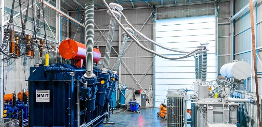
4. Factory Acceptance Testing (FAT) – Pre-Delivery Verification
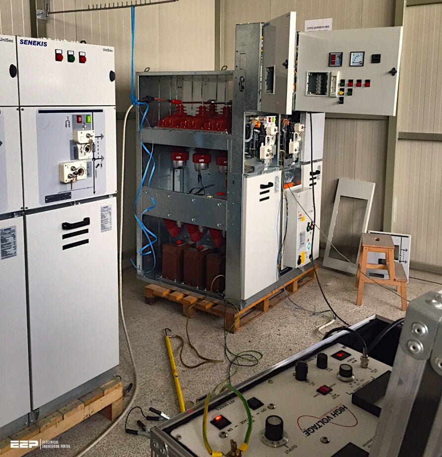
Factory Acceptance Testing is the formal verification of equipment at the manufacturer’s works before dispatch to site. It is one of the most important milestones in a substation project because it provides an opportunity to identify issues before equipment reaches a live site environment.
4.1 What FAT Proves?
FAT confirms that the manufactured electrical equipment unit:
- Matches approved drawings and specifications
- Is electrically healthy
- Has been wired correctly
- Performs intended functions correctly
- Is ready for installation and subsequent site testing
Unlike type testing, FAT is not about proving the design concept under extreme conditions. It is about proving the delivered product.
While all electrical panels are expected to be fault-free upon arrival from the subcontractors responsible for their assembly, defects may occasionally arise. Consequently, these manufacturing acceptance tests are essential.
During a FAT, all installations and wirings are verified to ensure they conform to the project-specific drawings. Functions intended to operate upon panel installation at the site are also simulated to verify automated capability. All potential problems, deviations, and requests are duly recorded.
Watch Video – Testing, Commissioning & Troubleshooting
4.2 FAT as a Quality Gate
FAT serves as a formal quality checkpoint between manufacturing and site delivery. In utility projects, especially in the UK and Middle East, equipment is often not allowed to leave the factory until FAT has been completed, observations are closed, and documentation is signed off.
4.3 FAT and Client Confidence
FAT is usually witnessed by:
- The client
- Consultant
- EPC contractor
- Third-party inspector
- Commissioning representative
This witnessed approach builds confidence and ensures that issues are challenged before dispatch rather than after installation.
Figure 5 – Example of FAT check list

4.4 FAT in Substations – Concept and Scope
It is important to understand that “substation FAT” does not mean one single FAT for the entire substation. A substation is a collection of primary and secondary components, each with its own design standards, testing requirements, and functional responsibilities.
Therefore, substation FAT is more accurately understood as the collective FAT of all major substation equipment.
Related electrical guides & articles


Muhammad Kashif
Muhammad Kashif Shamshad is an Electrical Engineer and has more than 17 years of experience in operation & maintenance, erection, testing project management, consultancy, supervision, and commissioning of Power Plant, GIS, and AIS high voltage substations ranging up to 500 kV HVAC & ±660kV HVDC more than ten years experience is with Siemens Saudi Arabia.Profile: Muhammad Kashif
