
Estimated Study Time: 26 minutes
Substation Grounding
Grounding at power substations is extremely important. The grounding system provides the ground connection for the grounded neutral for transformers, reactors, and capacitors and also the discharge path for lightning rods, arresters, gaps, and similar devices. It ensures safety to operating personnel by limiting potential differences, which can exist in a substation.
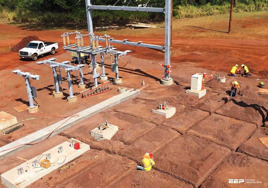 Practical steps in the design of a substation grounding (photo credit: Pacific Power Electrical Contracting LLC)
Substation grounding provides a means of discharging and de-energizing equipment in order to proceed with maintenance on the equipment.
It also provides a sufficiently low-resistance path to the ground to minimize the rise in ground potential with respect to remote ground.
Substation safety requirements call for the grounding of all exposed metal parts of switches, structures, transformer tanks, metal walkways, fences, steelwork of buildings, switchboards, instrument transformer secondaries, etc. This means that a person touching or near any of this equipment cannot receive a dangerous shock if a high-tension conductor flashes to or comes in contact with any of the equipment listed.
This means that each individual piece of equipment, each structural column, etc., must have its own connection to the station grounding mat.
A most useful source of information concerning substation grounding is contained in the comprehensive guide IEEE Standard 80, IEEE Guide for Safety in AC Substation Grounding.
Much of the following information is based on recommendations stated in the IEEE Standard 80.
Practical design of a grounding grid
The basic substation ground system used by most utilities takes the form of a grid of horizontally buried conductors. The reason that the grid or mat is so effective is attributed to the following:
Reason #1 – In systems where the maximum ground current may be very high, it is seldom possible to obtain a ground resistance so low as to ensure that the total rise of the grounding system potential will not reach values unsafe for human contact.
This being the case, the hazard can be corrected only by control of local potentials. A grid is usually the most practical way to do this.
Reason #2 – In HV and EHV substations, no ordinary single electrode is adequate to provide needed conductivity and current-carrying capacity.
However, when several are connected to each other and to structures, equipment frames, and circuit neutrals which are to be grounded, the result is necessarily a grid, regardless of original objectives. If this grounding network is buried in soil of reasonably good conductivity, this network provides an excellent grounding system.
Within the grid, cables should be laid in parallel lines and at reasonably uniform spacing.
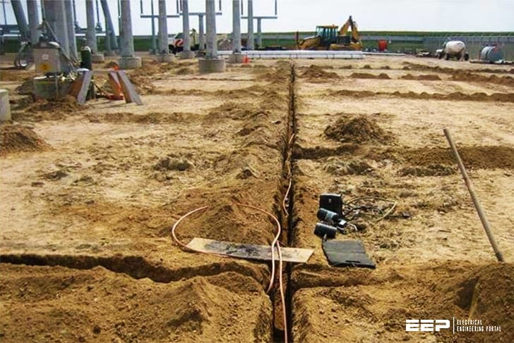
They should be located, where practical, along rows of structures or equipment to facilitate the making of ground connections. The preliminary design should be adjusted so that the total length of buried conductor, including cross connections and rods, is at least equal to that required to keep local potential differences within acceptable limits.
A typical grid system for a substation might comprise 4/0 bare stranded copper cable buried 12 to 18 in below grade and spaced in a grid pattern of about 10 by 20 ft. Other conductor sizes, burial depths, and grid conductor spacings, however, are frequently used.
At each junction of 4/0 cable, the cables would be securely bonded together, and there might also be connected a driven copper-covered steel rod approximately 5/8 in. in diameter and approximately 8 ft long.
In very high-resistance soils it might be desirable to drive the rods deeper.
A typical grid system usually extends over the entire substation yard and sometimes a few feet beyond the fence, which surrounds the building and equipment. Figure 1 shows a grounding plan for a typical EHV substation operating at 345 kV.

In order to ensure that all ground potentials around the station are equalized, the various ground cables or buses in the yard and in the substation building should be bonded together by heavy multiple connections and tied into the main station ground.
This is necessary in order that appreciable voltage differences to ground may not exist between the ends of cables which may run from the switchyard to the substation building.
Copper cables or straps are usually employed for equipment-frame ground connections.
However, transformer tanks are sometimes used as part of the ground path for lightning arresters mounted thereon. Similarly, steel structures may be used as part of the path to ground if it can be established that the conductivity, including that of any joints, is and can be maintained as equivalent to the copper conductor that would otherwise be required.
Related electrical guides & articles


Edvard Csanyi
Hi, I'm an electrical engineer, programmer and founder of EEP - Electrical Engineering Portal. I worked twelve years at Schneider Electric in the position of technical support for low- and medium-voltage projects and the design of busbar trunking systems.I'm highly specialized in the design of LV/MV switchgear and low-voltage, high-power busbar trunking (<6300A) in substations, commercial buildings and industry facilities. I'm also a professional in AutoCAD programming.
Profile: Edvard Csanyi
